Crane sling power generation system, crane sling and crane

A technology for power generation systems and cranes, which is applied in the direction of cranes, motor/generator/inverter limiters, motor generator control, etc. It can solve the problems of affecting the operation performance of cranes, illegal and complicated wiring layout, and reducing the service life of cables, etc. , to achieve the effects of reducing oil pollution, saving fuel consumption and increasing power generation capacity

Inactive Publication Date: 2009-05-27
SANY MARINE HEAVY IND
View PDF0 Cites 20 Cited by
  • Summary
  • Abstract
  • Description
  • Claims
  • Application Information

AI Technical Summary

Problems solved by technology

The layout of the special cables needs to cross the lifting beam of the crane, the line is relatively long, and the wiring layout is illegal and complicated; in addition, during the lifting operation, t...

Method used


Image

  • Crane sling power generation system, crane sling and crane
  • Crane sling power generation system, crane sling and crane
  • Crane sling power generation system, crane sling and crane

Examples


Embodiment 1

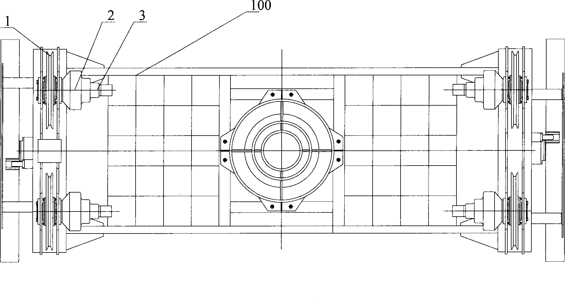
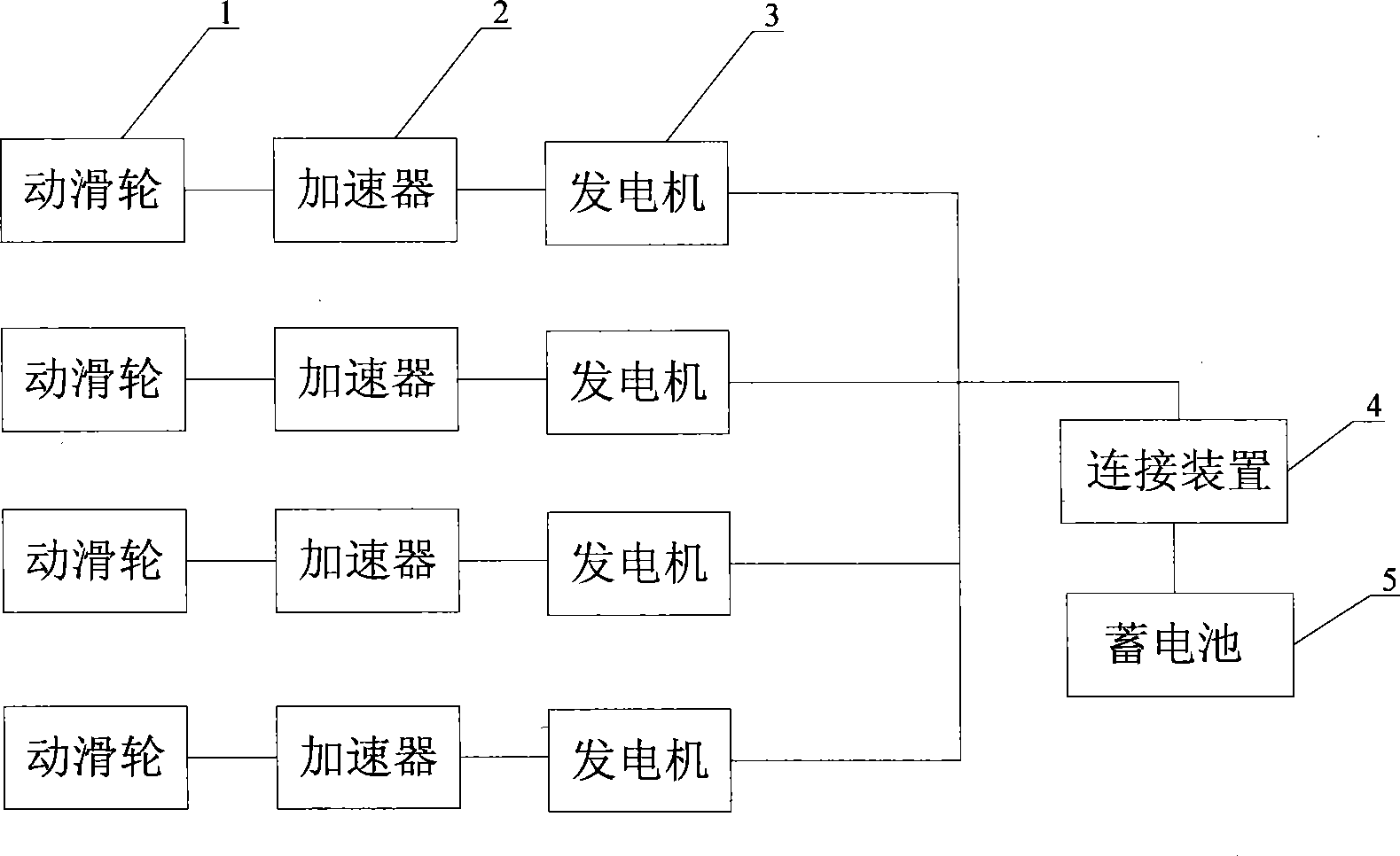
[0032] Embodiment 1 provides a crane spreader power generation system, combined with figure 1 and figure 2 , the crane spreader power generation system provided includes four movable pulleys 1, an accelerator 2, a generator 3, a connecting device 4 and a storage battery 5, and for the convenience of description, a spreader frame 100 is also shown in the figure. The movable pulley 1 is installed on the spreader frame 100 and can rotate around a fixed shaft; the four movable pulleys 1 form the movable pulley block of the crane, and the movable pulley block and the fixed pulley block can form the pulley mechanism of the crane to realize the rise and fall of the spreader. Corresponding to each movable pulley 1, four accelerators 2 are installed, and the accelerators 2 are installed between the rotating shaft of the movable pulley 1 and the rotor shaft of the generator 3. In this example, the accelerator 2 is a planetary accelerator, and its two ends are respectively connected wi...

Embodiment 2

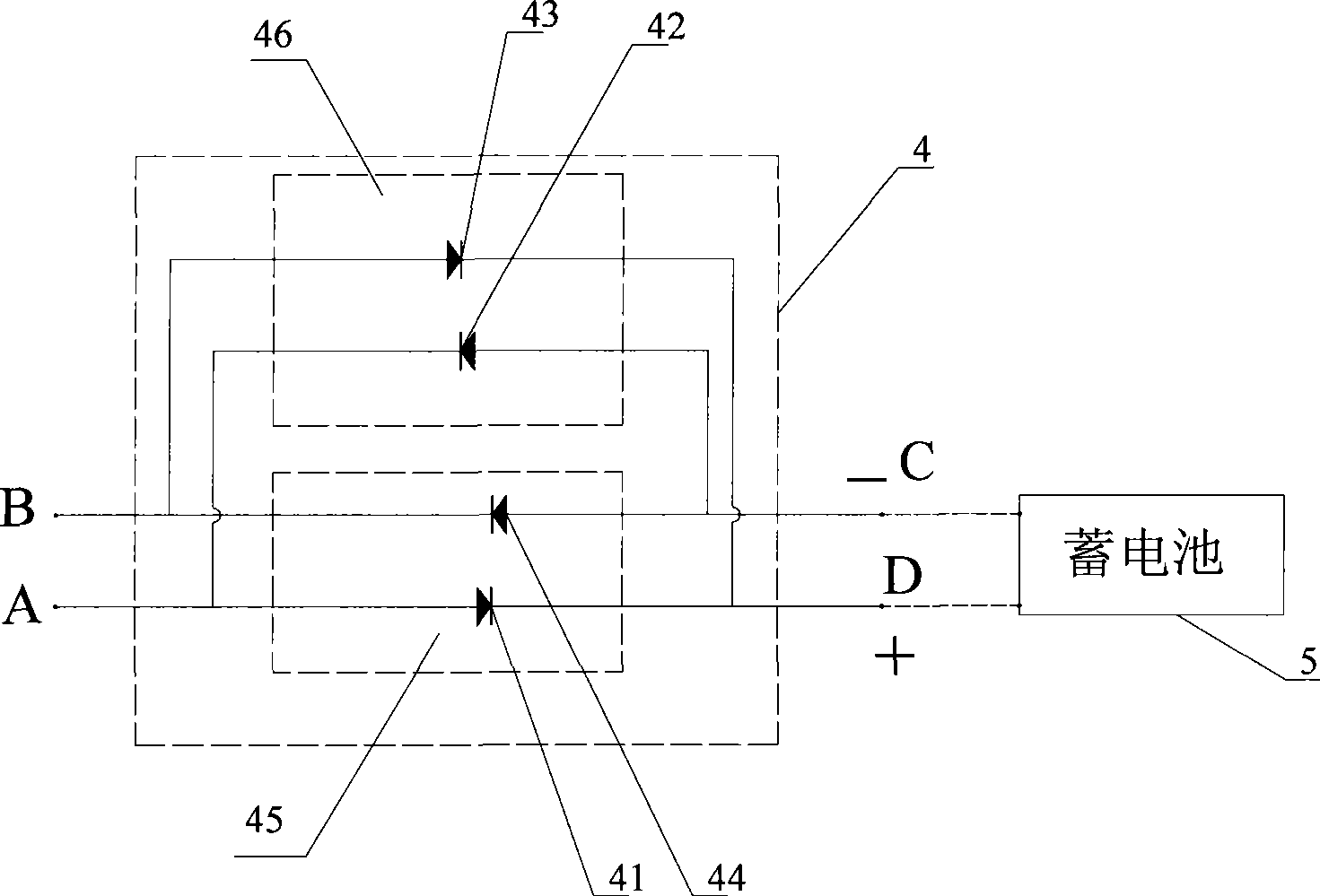
[0039] The working process of the crane spreader power generation system provided by Embodiment 2 is: when the battery 5 is fully charged, the travel switch 47 keeps the second one-way circuit 46 in the disconnected state, and the second one-way circuit 46 cannot connect the generator 3 to the battery. connected, the second one-way circuit 46 does not work; at this time, only the first one-way circuit 45 remains connected. When the sling is raised, the second output terminal B of the generator 3 is a high-voltage terminal, the first output terminal A is a low-voltage terminal, the diode of the first one-way circuit 45 is reversely cut off, the generator 3 cannot charge the storage battery 5, and the storage battery 5 Also can not discharge; When the sling is lowered, the first output terminal A of the generator 3 is a high-voltage terminal, the second output terminal B is a low-voltage terminal, and the diode of the first one-way circuit 45 is forward-conducting, so that the ge...


PUM


Abstract

The invention discloses a crane sling electricity-generating system, a crane sling and a crane. The crane sling electricity-generating system comprises a movable pulley, a generator and a storage battery, wherein the movable pulley is arranged on a crane sling frame and is connected with a fixed pulley block on a crane jib through a wirerope; during rotation, the movable pulley can drive a rotor shaft of the generator to rotate; an output end of a generator circuit is connected with the storage battery through a connection device; and when the sling moves down, the connection device ensures that the generator charges the storage battery. The crane sling electricity-generating system can make full use of the kinetic energy of the movable pulley to generate electric energy; the generated electric energy can be used to drive a telescopic mechanism and a rotary mechanism of the sling, and can also be used in other aspects of the crane so as to reduce oil consumption of the crane; meanwhile, hydraulic oil pollution can be reduced and environmental protection performance of the crane can be improved; in addition, the layout of a crane feeding circuit is simplified to optimize the service performance of the crane.

Description

technical field [0001] The invention relates to a crane technology, in particular to a crane sling power generation system, and also relates to a crane sling with a crane sling power generation system and a crane with a sling. Background technique [0002] The crane spreader is the part that is directly in contact with the container. The crane grabs the container through the spreader and transports it to the predetermined location. A movable pulley block is installed on the upper frame of the spreader, and the movable pulley of the movable pulley block is connected with the fixed pulley block on the trolley mechanism through a steel wire rope, and the trolley mechanism can drive the spreader to rise or fall through the steel wire rope. [0003] When the spreader moves, especially when the spreader is lowered, the friction between the wire rope and the movable pulley will make each movable pulley of the movable pulley block rotate, and a part of the potential energy of the sp...

Claims


Application Information

Patent Timeline
IPC IPC(8): B66C17/20B66D1/02B66C1/10B66C13/12H02J7/00H02P3/18
Inventor 杨成勇廖德彦
Owner SANY MARINE HEAVY IND
Why Eureka
Try Eureka