
Steel box-concrete combined box plate arch structure and construction method thereof

A construction method, steel box arch technology, applied in the direction of arch bridges, erection/assembly bridges, bridge materials, etc., can solve the problems of complex construction technology, large structural deformation, poor safety, etc., and achieve good comprehensive technical and economic benefits, good strength And the effect of anti-deformation ability and reliable connection performance

Inactive Publication Date: 2009-05-27
CHONGQING JIAOTONG UNIVERSITY
View PDF0 Cites 11 Cited by
  • Summary
  • Abstract
  • Description
  • Claims
  • Application Information

AI Technical Summary

Problems solved by technology

[0003] However, concrete arch bridges have the disadvantages of high construction site and equipment requirements, complex construction technology, long construction period, and poor safety; the concrete arch formed by segmental prefabricated hoisting connections usually has many vertical and horizontal joints in the structure, which easily leads to the actual state of the structure. There are obvious deviations from the ideal design state, and the seismic performance of the concrete arch bridge is poor; while the steel structure arch bridge is simply used, the amount of steel will increase significantly, resulting in high cost, and the stiffness of the steel structure arch bridge is relatively low, and the structure deforms under the load Larger, does not have comprehensive technical and economic advantages for arch bridges with a span of less than 200 meters

Method used


Image

  • Steel box-concrete combined box plate arch structure and construction method thereof
  • Steel box-concrete combined box plate arch structure and construction method thereof
  • Steel box-concrete combined box plate arch structure and construction method thereof

Examples


Embodiment Construction

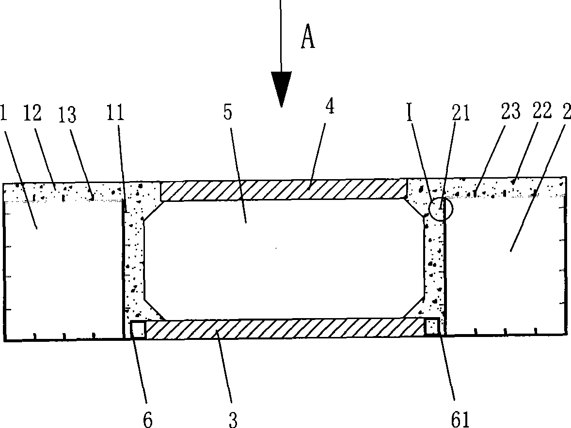
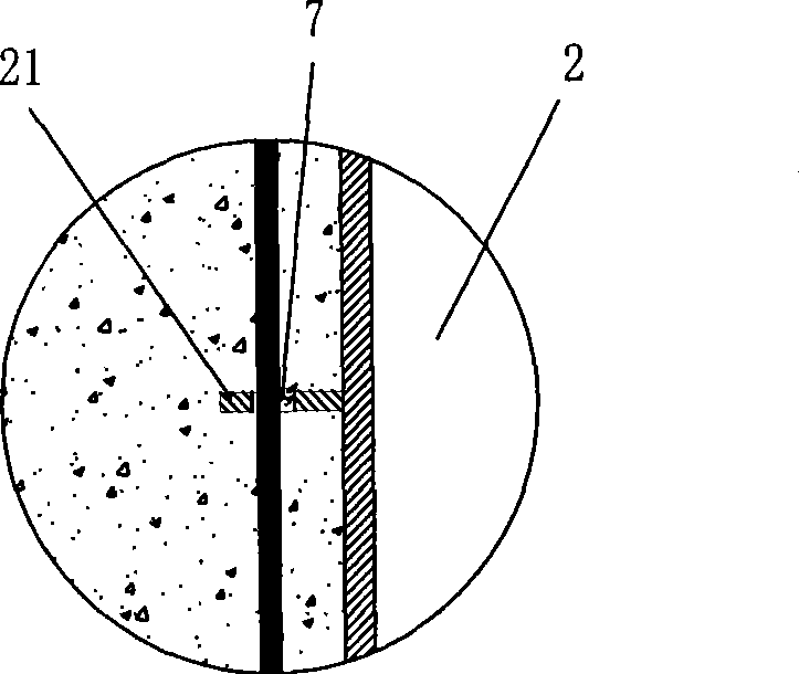
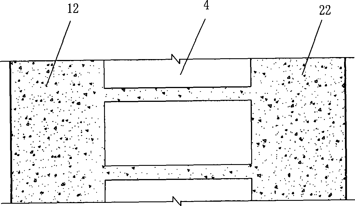
[0027] figure 1 It is a schematic diagram of the cross-sectional structure of the mid-span section of the present invention, figure 2 for figure 1 Enlarged view at I, image 3 for figure 1 Along the schematic diagram of A, Figure 4 It is a schematic diagram of the cross-sectional structure of the arch foot section of the present invention, Figure 5 for Figure 4 Schematic diagram along direction B, Figure 6 It is a schematic diagram of the arch structure of the present invention. The steel box-concrete composite box-slab arch structure of the present embodiment includes steel box arch I 1 and steel box arch II 2 arranged in parallel, the bottom plate of steel box arch I 1 and steel box arch II 2 The bottom prefabricated slabs 3 are arranged vertically side by side between the bottom plates of the steel box arch I1 and the top plate of the steel box arch II 2. The bottom plates of 2 respectively extend laterally to the inside, and the two ends of the bottom prefabric...


PUM


Abstract

The invention discloses a steel box-concrete combined box plate arch structure and a construction method thereof. Bottom precast slabs and top precast slabs are abreast arranged between a steel box arch I and a steel box arch II in parallel arrangement along the longitudinal direction; two ends of the bottom precast slab are supported on the extension parts formed through transversely extending a soleplate of the steel box arch I and a base plate of the steel box arch II towards the inner side respectively; and the steel box-concrete combined box plate arch structure of which the middle part has a concrete box structure is formed between two ends of the top precast slab and two ends of the bottom precast slab and the steel box arch I and a steel box arch II, between the adjacent bottom precast slabs and between the adjacent top precast slabs through cast-in-place concrete. The construction method obviously simplifies a main arch construction process, reduces anticipation to precast field and hoisting equipment, improves safety degree of the structure and personnel in the construction period, reduces engineering risk, shortens construction period and has remarkable comprehensive technical and economic benefits.

Description

technical field [0001] The invention belongs to the field of building structures and bridge road engineering, in particular to a steel box-concrete combined box-slab arch structure and a construction method thereof. Background technique [0002] Concrete arch bridge is favored by people for its beautiful shape, low cost, strong spanning force, economy and practicality, and has become one of the most commonly used bridge types in my country. Common arch bridges include main arches, columns on the main arches, bridge slabs and other arch structures. The main arch is the main load-bearing structure of the arch bridge. The arch bridge avoids the construction of high piers and towers, saves the construction cost of the substructure, and its construction materials are mainly materials with low unit prices such as concrete and ordinary steel; the concrete arch bridge with good construction quality also has the advantages of durability and post-maintenance The advantage of low cost...

Claims


Application Information

Patent Timeline
Patent Type & Authority Applications(China)
IPC IPC(8): E01D4/00E01D21/00E01D22/00E01D101/24E01D101/30
Inventor 周志祥吴海军
Owner CHONGQING JIAOTONG UNIVERSITY
Learn More