Clutch actuating mechanism of automatic mechanical speed variator

A technology for automatic transmissions and actuators, applied in the direction of non-mechanical drive clutches, electric clutches, fluid drive clutches, etc., can solve the problems of complex transmission methods, complex parts, and difficult processing, and achieve stable transmission, high precision, The effect of accelerating the separation speed

Active Publication Date: 2009-05-27
CHONGQING TSINGSHAN IND
View PDF0 Cites 18 Cited by
  • Summary
  • Abstract
  • Description
  • Claims
  • Application Information

AI Technical Summary

Problems solved by technology

Although these two methods can make the clutch disengage and combine, the transmission methods adopted by the two methods are relatively complicated, and the parts are complicated and difficult to process. poor effect

Method used


Image

  • Clutch actuating mechanism of automatic mechanical speed variator
  • Clutch actuating mechanism of automatic mechanical speed variator
  • Clutch actuating mechanism of automatic mechanical speed variator

Examples


Embodiment 1

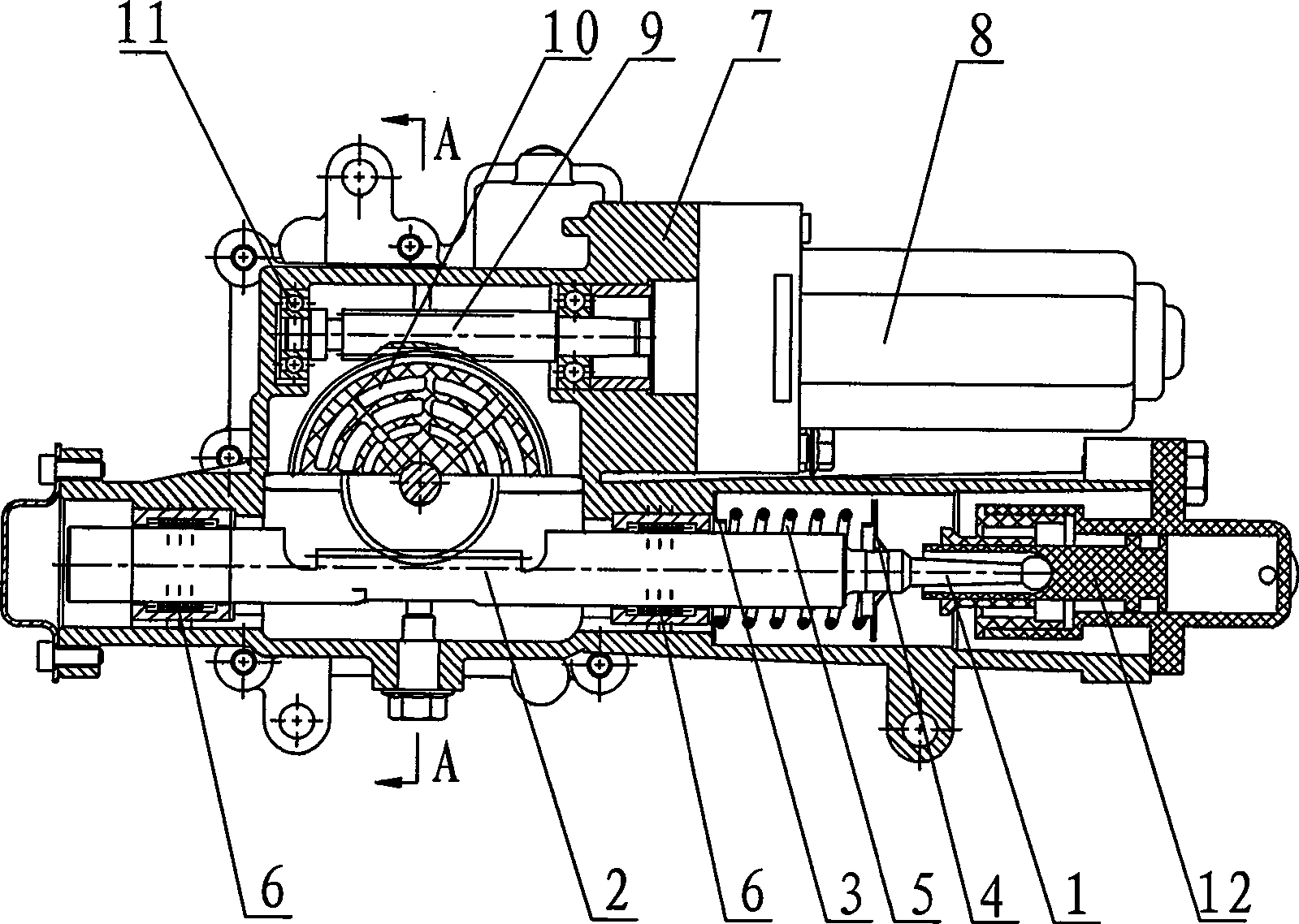
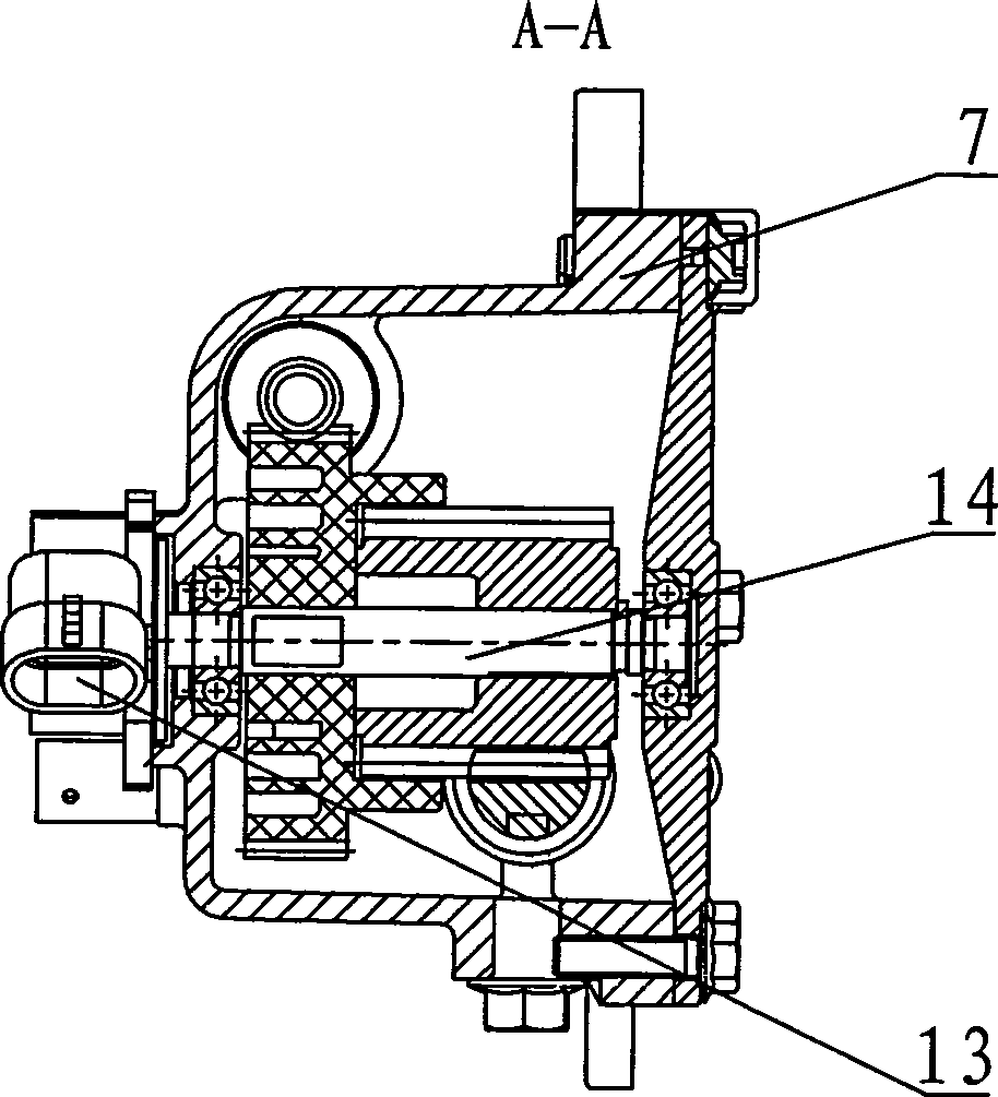
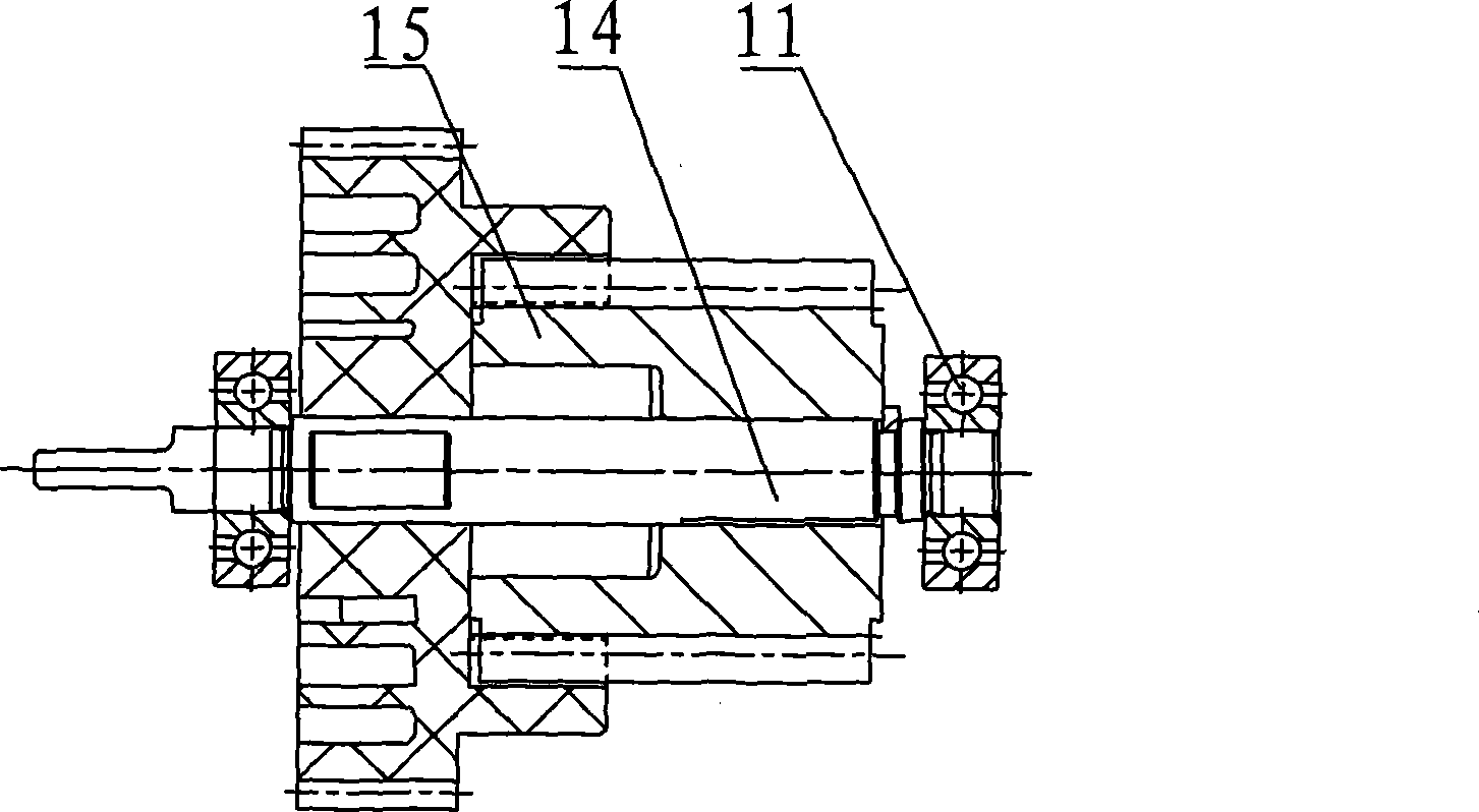
[0020] Example 1, such as figure 1 , 2 . As shown in 3, a mechanical automatic transmission clutch actuator includes a clutch driving device and a clutch master cylinder assembly. The clutch driving device includes a clutch motor 8, a clutch motor worm 9, a clutch motor worm wheel 10 and a clutch The clutch gear 15 engaged by the motor worm gear 10; the clutch master cylinder assembly includes a master cylinder piston 12, which is characterized in that a clutch rack assembly is arranged in the clutch housing 7, and the clutch driving device passes through the clutch rack assembly Connect with the clutch master cylinder assembly.

[0021] The clutch rack assembly includes a clutch rack 2 with a clutch rack push rod 1, a spring guide sleeve 3, a clutch rack block 4 and a clutch master cylinder preload spring 5. The clutch rack push rod 1 Connected with the clutch master cylinder assembly, the clutch rack 2 is set in the clutch housing 7 through a linear bearing 6, the spring g...


PUM


Abstract

The invention relates to a mechanical automatic speed changer clutch actuating mechanism. The mechanism comprises a clutch driving device and a clutch master cylinder assembly, wherein the clutch driving device comprises a clutch electric motor (8), a clutch electric motor worm (9), a clutch electric motor worm wheel (10) and a clutch gear (15) engaged with the clutch electric motor worm wheel (10); and the clutch master cylinder assembly comprises a master cylinder piston (12). The mechanical automatic speed changer clutch actuating mechanism is characterized in that the inside of a clutch casing (7) is provided with a clutch rack assembly; and the clutch driving device is connected with the clutch master cylinder assembly through the clutch rack assembly. Due to the adoption of the technical proposal, the mechanical automatic speed changer clutch actuating mechanism has the advantages of simple structure and smooth transmission.

Description

technical field [0001] The invention relates to a mechanical automatic transmission clutch actuator. Background technique [0002] The existing mechanical automatic transmission clutch actuator generally adopts two methods of motor control and hydraulic control. The motor control mainly adopts the structure of a motor with a screw and a nut. The rotation of the motor drives the screw to rotate, and the rotation of the screw drives The nut reciprocates to realize the separation and combination of the clutch; the hydraulic control mainly adopts a motor-crank-connecting rod structure, and the motor drives the movement of the crank-connecting rod mechanism to drive the reciprocating movement of the piston of the hydraulic cylinder to realize the separation and connection of the clutch. combined. Although these two methods can make the clutch disengage and combine, the transmission methods adopted by the two methods are relatively complicated, and the parts are complicated and d...

Claims


Application Information

Patent Timeline
Patent Type & Authority Applications(China)
IPC IPC(8): F16D25/12F16D28/00F16D29/00
Inventor 王海兵李培军龚为伦沈波姚文博蔡之骏
Owner CHONGQING TSINGSHAN IND
Why Eureka
Try Eureka