Glasses lens and lens module

A lens module and lens technology, applied in the field of photography, can solve the problems of destroying the imaging quality of the lens module 100, reducing image quality, and forming spots in the image, so as to achieve the effects of preventing spots, eliminating transmission paths, and improving image plane contrast

Inactive Publication Date: 2009-05-27
HONG FU JIN PRECISION IND (SHENZHEN) CO LTD +1
View PDF0 Cites 5 Cited by
  • Summary
  • Abstract
  • Description
  • Claims
  • Application Information

AI Technical Summary

Problems solved by technology

Especially in the region where the fixed part 132 of the lens module 100 is close to the optical part 131, the phenomenon of stray light is more serious, resulting in a decrease in image plane contrast and MTF (Modulation Transfer Function, Modulation Transfer Function), and spots are formed on the image, thereby destroying the lens module. Image Quality of Group 100

Method used


Image

  • Glasses lens and lens module
  • Glasses lens and lens module
  • Glasses lens and lens module

Examples


Embodiment Construction

[0015] The lens and lens module provided by the technical solution will be further described in detail below in conjunction with the accompanying drawings and multiple embodiments.

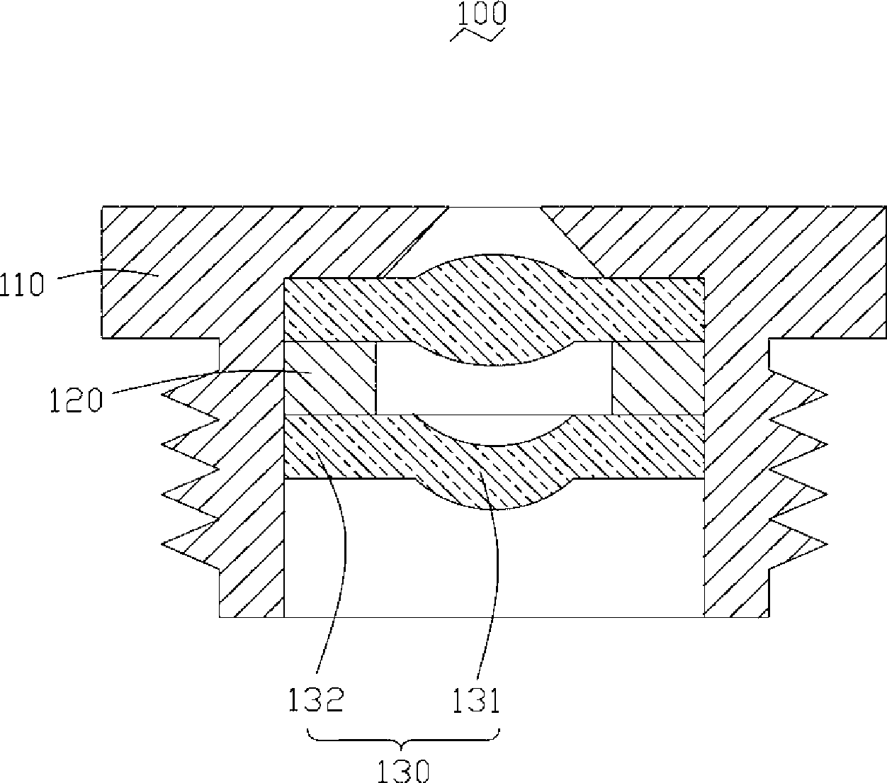
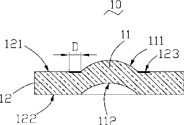
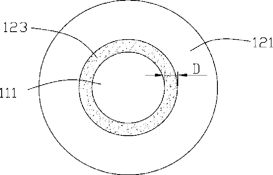
[0016] see figure 2 and image 3 , is the lens 10 provided by the first embodiment of the technical solution, which includes an optical portion 11 located at the center of the lens 10 and a fixing portion 12 surrounding the optical portion 11 and connecting with the optical portion 11 .

[0017] The optical part 11 is an effective optical imaging area, which is used to make the light beam pass through and form an image. The optical part 11 has a first optical surface 111 and a second optical surface 112 opposite to the first optical surface 111 . The first optical surface 111 and the second optical surface 112 can be spherical or aspheric.

[0018] The fixing portion 12 is used for fixing the lens 10 and has a first surface 121 and a second surface 122 opposite to the first surface 121 . The ...


PUM


Abstract

The invention provides a lens, comprising an optical section and a fixed section connecting and surrounding the optical section. The optical section is used for making the optical beam pass-by and image, which is characterized in that the fixed section is provided with at least a rough face connected with the optical section for scattering the heterogeneous light. Additionally, the invention also relates to a lens module adopting the lens, not only scattering the heterogeneous light, but also reducing to generate the heterogeneous light, and improving the imaging quality of the lens module.

Description

technical field [0001] The invention relates to the technical field of photography, in particular to a lens and a lens module using the lens. Background technique [0002] With the multi-functional development of electronic products, lens modules have become key components of camera devices widely used in consumer electronics products such as digital cameras, video cameras, personal digital assistants and mobile phones with camera functions. [0003] Such as figure 1 As shown, generally, the lens module 100 includes a lens barrel 110 , two lenses 130 disposed in the lens barrel 110 and a spacer 120 between the two lenses 130 . The spacer 120 is located between the two lenses 130 for spacing the two lenses 130 so as to prevent the two lenses 130 from contacting each other and being worn. The lens 130 includes an optical portion 131 and a fixing portion 132 surrounding the optical portion 131 . The optical part 131 is used to completely transmit the light beam and focus the...

Claims


Application Information

Patent Timeline
Patent Type & Authority Applications(China)
IPC IPC(8): G02B7/02G02B7/04
Inventor 颜士杰
Owner HONG FU JIN PRECISION IND (SHENZHEN) CO LTD
Why Eureka
Try Eureka