Six-phase switch reluctance motor system

A technology of reluctance motor and switched reluctance, which is applied in the field of motor system, can solve the problems of torque pulsation and large noise, and achieve the effects of reducing torque pulsation, reducing noise, and improving running stability

A technology of reluctance motor and switched reluctance, which is applied in the field of motor system, can solve the problems of torque pulsation and large noise, and achieve the effects of reducing torque pulsation, reducing noise, and improving running stability

CN101442247AInactive Publication Date: 2009-05-27BEIJING CHINA TEX MECHANICAL & ELECTRICAL ENG

Image

  • Six-phase switch reluctance motor system
  • Six-phase switch reluctance motor system
  • Six-phase switch reluctance motor system

Examples


Embodiment Construction

[0037] The technical solutions of the present invention will be further described in detail below through the accompanying drawings and embodiments.

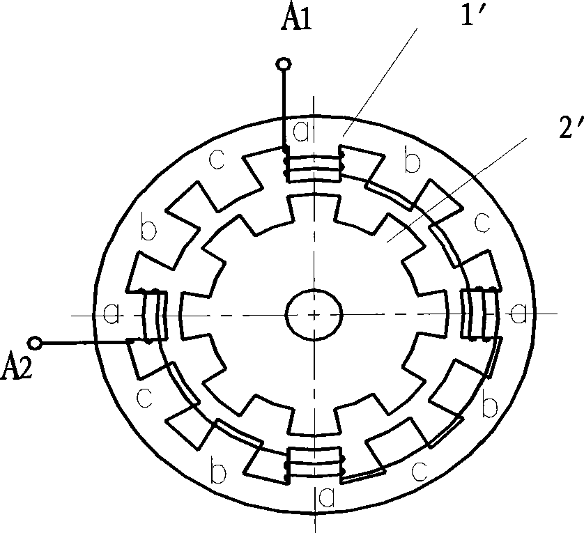
[0038] Based on the existing 3-phase 12 / 8-pole reluctance motor system, the invention only changes the winding connection mode to realize the 6-phase 12 / 10-pole reluctance motor system without changing the number of salient poles and coils of the motor stator. like Image 6 Shown is a schematic diagram of the same pole arrangement of each phase winding of the motor of the present invention; Figure 7 It is a schematic diagram of the different pole arrangement of each phase winding of the motor of the present invention. The stator iron core 1 is the same as the stator iron core 1 of the existing 3-phase 12 / 8-pole motor, but the coils on the two salient poles facing each other on the iron core 1 are connected (in series or in parallel) to form a 1-phase winding, Respectively a, b, c, d, e, f, a total of 6-phase windings, only th...


PUM


Abstract

The invention relates to a six-phase switched reluctance motor system, which comprises a switched reluctance motor, a power circuit, an angular displacement sensor and a control circuit, wherein the switched reluctance motor is a six-phase winding switched reluctance motor. Therefore, the six-phase switched reluctance motor system achieves a six-phase motor system based on the prior three-phase 12 / 8-stage motor system so as to double the phase number without increasing complexity of the system, reduce torque ripple during running of the motor greatly, improve running stability, and reduce noise.

Description

technical field [0001] The invention relates to the field of motor systems, in particular to a 6-phase switched reluctance motor system. Background technique [0002] In recent years, switched reluctance motor technology has been widely used at home and abroad. [0003] The switched reluctance motor system is mainly composed of four parts: motor, power circuit, angular displacement sensor and control circuit. [0004] There are many types of motor parts in the switched reluctance motor system. The commonly used structures are 2-phase 4 / 2 poles, 3-phase 6 / 4 poles, 3-phase 12 / 8 poles, 4-phase 8 / 6 poles, 5-phase 10 / 8 poles . Different structural types have different performance characteristics and are suitable for different applications. Generally speaking, the fewer the number of phases, the simpler the structure of each part of the motor system and the lower the cost, but some of its functions and performance indicators are also lower. [0005] Among them, the 2-phase sys...

Claims


Application Information

Patent Timeline
27 May 2009
Publication
CN101442247A
IPC
H02K29/06; H02P6/00; H02P6/08; H02M5/44; H02P25/098
Inventors
裘锦灼; 高超