Optical transmission system and optical node

An optical node and optical transmission technology, applied in the field of optical transmission systems and optical nodes, can solve the problems of complex path management and non-existence of optical signals, and achieve the effect of easy path management

Inactive Publication Date: 2009-05-27
HITACHI LTD
View PDF1 Cites 12 Cited by
  • Summary
  • Abstract
  • Description
  • Claims
  • Application Information

AI Technical Summary

Problems solved by technology

However, issues such as the following have to be considered
That is, in the past, unnecessary alarms were generated because there was a possibility that there was no optical signal in the uplink direction.
Also, lane management becomes complicated due to the mix of 1-to-1 and 1-to-N lanes

Method used


Image

  • Optical transmission system and optical node
  • Optical transmission system and optical node
  • Optical transmission system and optical node

Examples


Embodiment 1

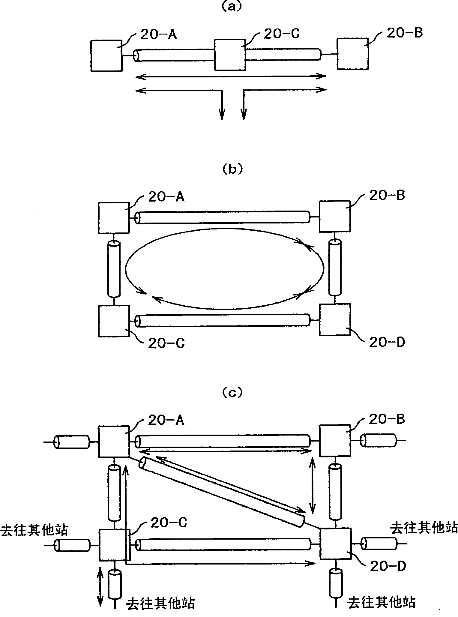
[0052] use figure 1 , indicating the network status. figure 1The structure of (a) is that there are two stations of station 20-A and station 20-B at the terminal, and station 20-C is arranged between station 20-A and station 20-B, and they are mutually connected with transmission line optical fiber. is a linear network in which at least a part of a signal that is added in station 20-A or station 20-B may be dropped in station 20-C, and other signals may be added in station 20-C. signal, such a network is linear. Here, arrows of solid lines indicate the state of path setting between the station 20-A and the station 20-B, between the station 20-A and the station 20-C, and between the station 20-C and the station 20-B.

[0053] figure 1 (b) is a ring network. In the ring network, a station 20-A, a station 20-B, a station 20-C, and a station 20-D are respectively connected to adjacent stations 20 with transmission line optical fibers. Since the network forms a ring, even if a...

Embodiment 2

[0087] Control of branch insertion when a receiving node is added in an optical transmission system will be described using FIGS. 8 and 9 . In FIG. 8 , the optical transmission system 10 is set as a 1-to-N optical path in which station A is the sending node, and stations B and C are receiving nodes. The flow of signals in this state is shown by thick solid lines. The state of the branch function unit 140 and the add function unit 150 of the WDM optical switch unit 40 at this time is shown in the column before addition in FIG. 9 . In addition, in FIG. 9, the branch function part is shown as "D", and the insertion function part is shown as "A". In addition, "—" in the picture means it doesn't matter, and "↑" means the same as above. Furthermore, the insertion function part is a device that can use a 1×2 optical switch or a WSS, and its function is a selector.

[0088] Returning to FIG. 8 , the case where station D is added as a receiving node to the 1-to-N optical path of the...


PUM


Abstract

The invention provides an optical transmission system and optical node. On condition of a pair of 1 type gateways and a pair of N type gateways which are mixed, unexpected alarms will not be produced, and gateway management can be carried out as now. The optical transmission system comprises an integrated monitoring and controlling unit which is to control an optical add-drop unit so as to cause transmit signals from the optical transceiver of a first optical node to be received by the optical transceivers of plural different optical nodes, the purpose can be achieved by an optical transmission system provided with an alarm inhibiting device that can inhibit the optical transceiver, which is a source of transmission, from issuing any unexpected alarm.

Description

technical field [0001] The present invention relates to an optical transmission system and an optical node, in particular to an optical transmission system and an optical node that can be received by multiple nodes. Background technique [0002] Due to the surge of data traffic represented by the Internet, the transmission capacity of the communication network is developing toward a larger capacity. Large-capacity is achieved by converting transmission signals into light, using time-division multiplexing technology and optical wavelength multiplexing technology. In a transmission device with an average of 10 gigabits per second per channel, and in an optical fiber with several channels to dozens of channels, wavelength multiplexing can be performed using optical amplifiers or regenerative repeaters. Point-to-point type wavelength multiplexing transmission devices that transmit over long distances of several hundreds of km are put into practical use. [0003] In order to co...

Claims


Application Information

Patent Timeline
Patent Type & Authority Applications(China)
IPC IPC(8): H04J14/02H04B10/08H04B10/07H04B10/077H04B10/27H04B10/278H04B10/29
CPCH04J14/0212H04J14/0213H04J14/0204H04J14/0208
Inventor 深代康之
Owner HITACHI LTD
Why Eureka
Try Eureka