Real-time monitoring system of faults of overhead lines of distribution network

A real-time monitoring system, monitoring system technology, applied in the direction of fault location, etc., can solve problems such as difficult to promote, not well applied, and high investment cost

Active Publication Date: 2009-06-03
SHANGHAI MUNICIPAL ELECTRIC POWER CO +2
View PDF0 Cites 23 Cited by
  • Summary
  • Abstract
  • Description
  • Claims
  • Application Information

AI Technical Summary

Problems solved by technology

However, because the fault inspection mode has not been changed, there are still many deficiencies and defects in the function, and the lack of communication capabilities has not been well applied; if the distribution network automation system is used, it can realize automatic fault location, but due to the high input cost It is also difficult to effectively promote it; how to use mature communication technology to quickly upload the fault information collected by the overhead line fault indicator to the background monitoring system (computer), realize the rapid and automatic positioning of the fault section, and improve the fault It is very important and urgent to improve the performance of the indicator, improve its shortcomings, and increase the data communication function.

Method used


Image

  • Real-time monitoring system of faults of overhead lines of distribution network
  • Real-time monitoring system of faults of overhead lines of distribution network
  • Real-time monitoring system of faults of overhead lines of distribution network

Examples


Embodiment Construction

[0024] The structural features of the monitoring system of the present invention will be further described below in conjunction with the accompanying drawings and embodiments.

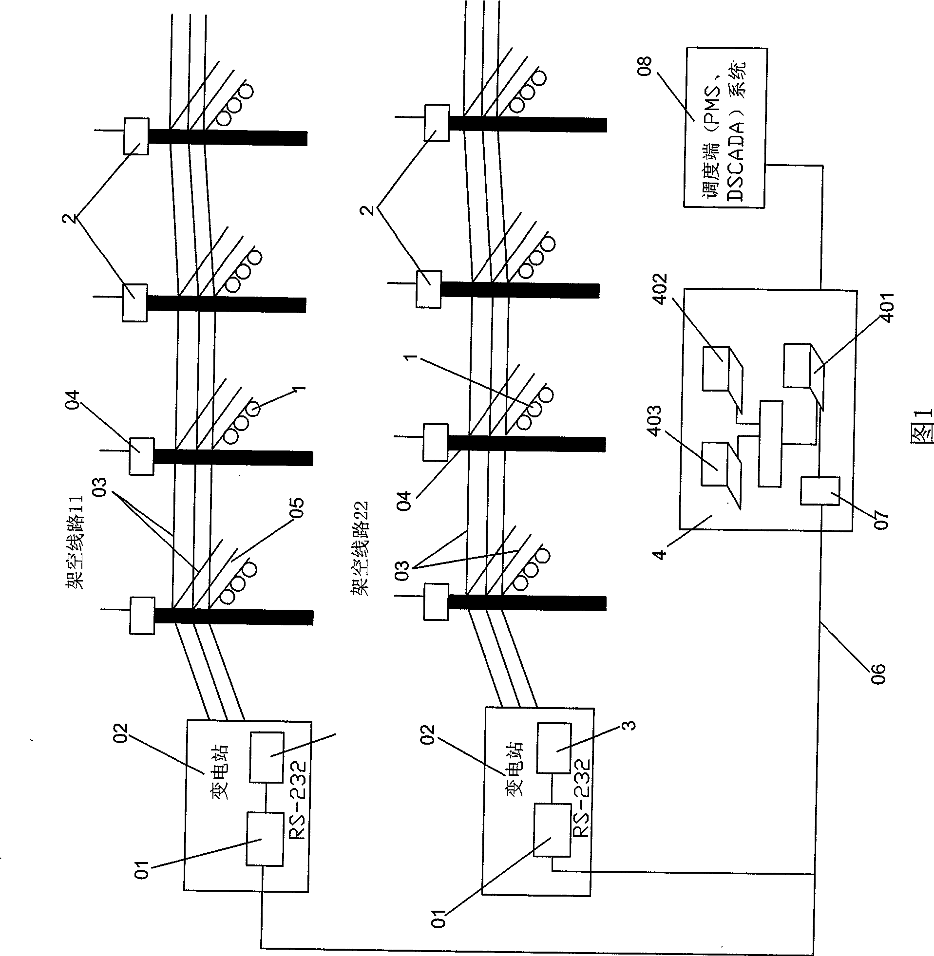
[0025] Fig. 1 is the structure of an embodiment of the monitoring system of the present invention. As shown in FIG. 1 , the monitoring system of the present invention includes an overhead line fault alarm 1 , a wireless repeater 2 , a wireless transceiver 3 and a background monitoring system 4 . As shown in FIG. 1 , in this embodiment, there are two overhead lines 11 and 22 . As shown in Figure 1, in the present embodiment, on each overhead line 11,22, there is an overhead line failure alarm 1 placed on the overhead line 03 on the branch line 05, and a wireless repeater 2 is placed on the branch line 05. On the utility pole 04, the wireless transceiver 3 is placed in the substation 02, and the wireless transceiver 3 is connected with the background monitoring system 4 through the optical fiber network...


PUM


Abstract

A real-time monitoring system of faults of overhead lines of a distribution network comprises a fault alarm of overhead lines arranged at the overhead lines of the distribution network, a wireless repeater which is arranged at an overhead line rod of the distribution network, a background monitoring system and a wireless transceiver which is connected between the wireless repeater and the background monitoring system. The fault alarm of the overhead lines transfers the detected real-time abnormal signals on the overhead lines and address information of the abnormal signals to the wireless repeater, the wireless repeater gradually transfers the information to the wireless transceiver through a relay link which is constituted by the wireless repeater, and the wireless transceiver further transfers the information to the background monitoring system for analysis, judgment and processing. The fault alarm of the overhead lines comprises a sensor, a signal acquisition unit, a microprocessor, a wireless RF module, a magnetoelectric conversion circuit, a power control module and a power supply. The real-time monitoring system can accurately and rapidly give out the faults, the abnormal information and occurrence addresses thereof on the overhead lines.

Description

technical field [0001] The invention relates to a real-time fault monitoring system for overhead line faults of distribution network for detecting faults on overhead lines of distribution network. Background technique [0002] With the rapid development of the national economic situation, the closely related power transmission and distribution network is also expanding rapidly, the power transmission line is expanding rapidly, the radius of power supply is expanding, and the number of branch lines is increasing, resulting in more and more complicated line structures and the occurrence of overhead lines. The possibility of failure is also gradually increasing. [0003] Once the overhead line fails, it is very difficult to find the fault branch and fault point; the query process is time-consuming and laborious, ranging from a few hours to dozens of hours, requiring a lot of manpower and material resources, causing great harm to the power company and users. Large economic loss...

Claims


Application Information

Patent Timeline
Patent Type & Authority Applications(China)
IPC IPC(8): G01R31/08
Inventor 关宏钱郁成严军姚建歆陈智芳徐洁鸣朱江韩跃峻张小越仲隽伟黄品磊沈韵
Owner SHANGHAI MUNICIPAL ELECTRIC POWER CO
Why Eureka
Try Eureka