
Solenoid type electromagnetic trip

An electromagnetic release and solenoid technology, which is applied to the operation/release mechanism of the protection switch, and the adjustment of the conditions of the protection switch, etc., can solve the problems of poor linearity, inconsistent initial state of the circuit breaker, and inability to adjust the short-circuit action current setting value. , to achieve the effect of reducing specifications and ensuring consistency

Active Publication Date: 2009-06-03
CHANGSHU SWITCHGEAR MFG CO LTD (FORMER CHANGSHU SWITCHGEAR PLANT)
View PDF1 Cites 6 Cited by
  • Summary
  • Abstract
  • Description
  • Claims
  • Application Information

AI Technical Summary

Problems solved by technology

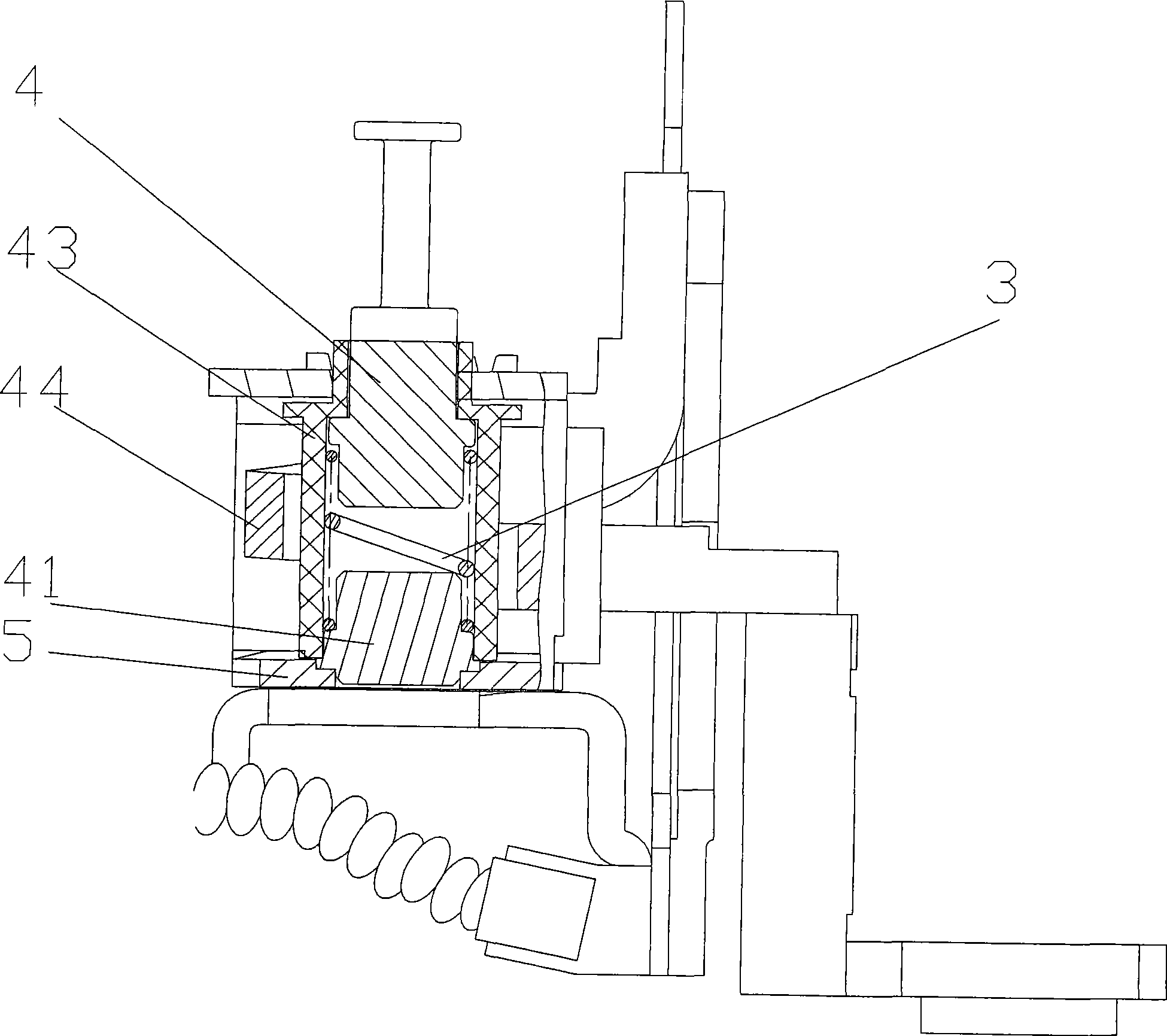
[0002] At present, the existing solenoid type electromagnetic tripper has a structure consisting of figure 1 As disclosed, it mainly includes a moving iron core 4, a static iron core 41, a spring 3, a coil 44, and a yoke 5. The spring 3 is installed between the moving iron core 4 and the static iron core 41, and is arranged for Inside the plastic sleeve 43 that insulates between the moving and static iron cores 4, 41 and the coil 44, the disadvantage of this structure is that the setting value of the short-circuit action current cannot be adjusted
But one of the shortcomings is that the adjustment of the magnetic gap is not easy to control, and the linearity is not good, so the one-time pass rate is very low in the actual mass production line; It is easy to cause inconsistency in the initial state between the releases of each phase in the circuit breaker

Method used


Image

  • Solenoid type electromagnetic trip
  • Solenoid type electromagnetic trip
  • Solenoid type electromagnetic trip

Examples


Embodiment

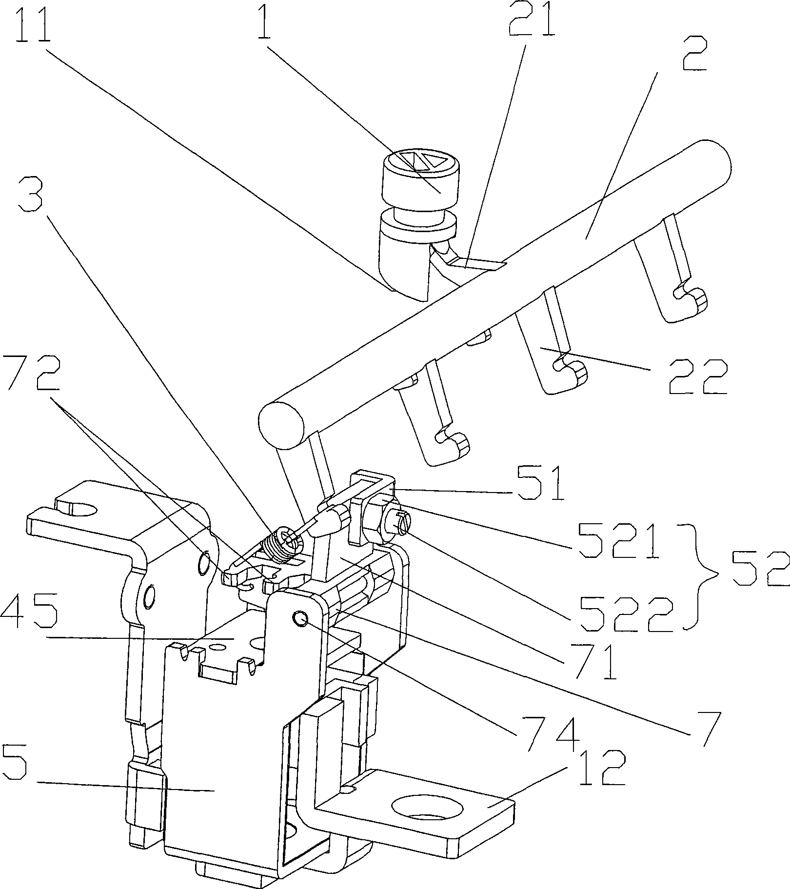
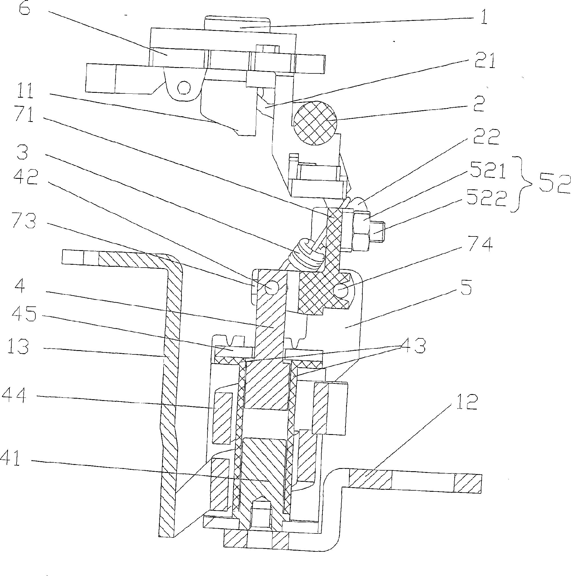
[0022] See figure 2 And combine image 3 , The solenoid type electromagnetic release of the present invention mainly includes knob 1, adjusting rod 2, spring 3, movable iron core 4, static iron core 41, plastic sleeve 43, coil 44, magnetic conductive plate 45, magnetic yoke 5, push Rod 7, and supporting parts. The knob 1 is installed on the bracket 6 in the base of the circuit breaker, and a spiral slope 11 is provided on the bottom of the knob 1. The adjusting rod 2 is rotatably pivoted on the bracket 6. A protrusion 21 is extended in the middle of the radial side of the adjusting rod 2, and the adjusting rod 2 is in contact with the spiral slope 11 at the bottom of the knob 1 through the protrusion 21 On the other side of the adjusting rod 2 in the radial direction, a first hook 22 for hooking one end of the spring 3 is also extended. The number of the first hook 22 is the same as the number of poles of the circuit breaker. There are four hooks 22, which can be applied to four-...


PUM


Abstract

The invention relates to a solenoid type electromagnetic trip, which belongs to the technical field of the low-voltage apparatus. The solenoid type electromagnetic trip comprises a knob, an adjusting rod, a spring, a moving iron core, a static iron core, a coil, a concentrating flux plate and a magnetic yoke and is characterized in that a push rod pivotally arranged at the upper end part of the magnetic yoke is also included, wherein, one end of the spring is connected with the adjusting rod, the other end of the spring is connected with the push rod, and the upper end of the moving iron core is movably connected with the push rod after penetrating the concentrating flux plate. The invention has the advantages that the linear regulation of the current setting value for the short circuit action is realized by adjusting the length of the spring through the knob; since the adjusting screw component is arranged on the magnetic yoke, the magnetic gap can be adjusted finely, the inconsistency of the current setting values of all the trips due to the parts and the assembly is eliminated, and the consistency of the initial states of all the trips is ensured; and at least one hanging hook is arranged on the upper edge of the push rod, so that the specification of the spring is reduced when the multi-gear adjustment is realized.

Description

Technical field [0001] The invention relates to a solenoid type electromagnetic release for a molded case circuit breaker, which is an improvement on the structure of the existing solenoid type electromagnetic release and belongs to the technical field of low-voltage electrical appliances. Background technique [0002] At present, the existing solenoid type electromagnetic trip unit is structured by figure 1 It is disclosed that it mainly includes a moving iron core 4, a static iron core 41, a spring 3, a coil 44, and a yoke 5. The spring 3 is installed between the moving iron core 4 and the static iron core 41, and is arranged for Inside the plastic sleeve 43 that insulates the moving and static iron cores 4, 41 and the coil 44, this structure has the disadvantage that the setting value of the short-circuit operating current is not adjustable. [0003] In addition, US invention patent No. 5467069 discloses "an adjustable circuit breaker device", which uses a solenoid type elect...

Claims


Application Information

Patent Timeline
IPC IPC(8): H01H71/24H01H71/74
Inventor 陈玉兵张洵初陈志刚管瑞良王炯华
Owner CHANGSHU SWITCHGEAR MFG CO LTD (FORMER CHANGSHU SWITCHGEAR PLANT)
Learn More