Supercharge Your Innovation With Domain-Expert AI Agents!

Reflow apparatus and method

A technology of a reflow device and a loader, which is applied to electric heating devices, electrical components, circuits, etc., can solve the problems of reducing the production volume and long time of the packaging process.

Inactive Publication Date: 2009-06-03
SAMSUNG ELECTRONICS CO LTD
View PDF5 Cites 4 Cited by
  • Summary
  • Abstract
  • Description
  • Claims
  • Application Information

AI Technical Summary

Problems solved by technology

The reflow step can take a considerable amount of time, thus reducing the throughput of the packaging process

Method used


Image

  • Reflow apparatus and method
  • Reflow apparatus and method
  • Reflow apparatus and method

Examples


Embodiment Construction

[0025] Preferred embodiments of the present inventive concept will be described in more detail below with reference to FIGS. 1 to 30 . The inventive concept, however, may be embodied in different forms and should not be construed as limited to the embodiments set forth herein. Rather, these embodiments are provided so that this disclosure will be thorough and complete, and these embodiments will fully convey the scope of the inventive concept to those skilled in the art. Accordingly, the size of elements in the drawings may be exaggerated for clarity of illustration.

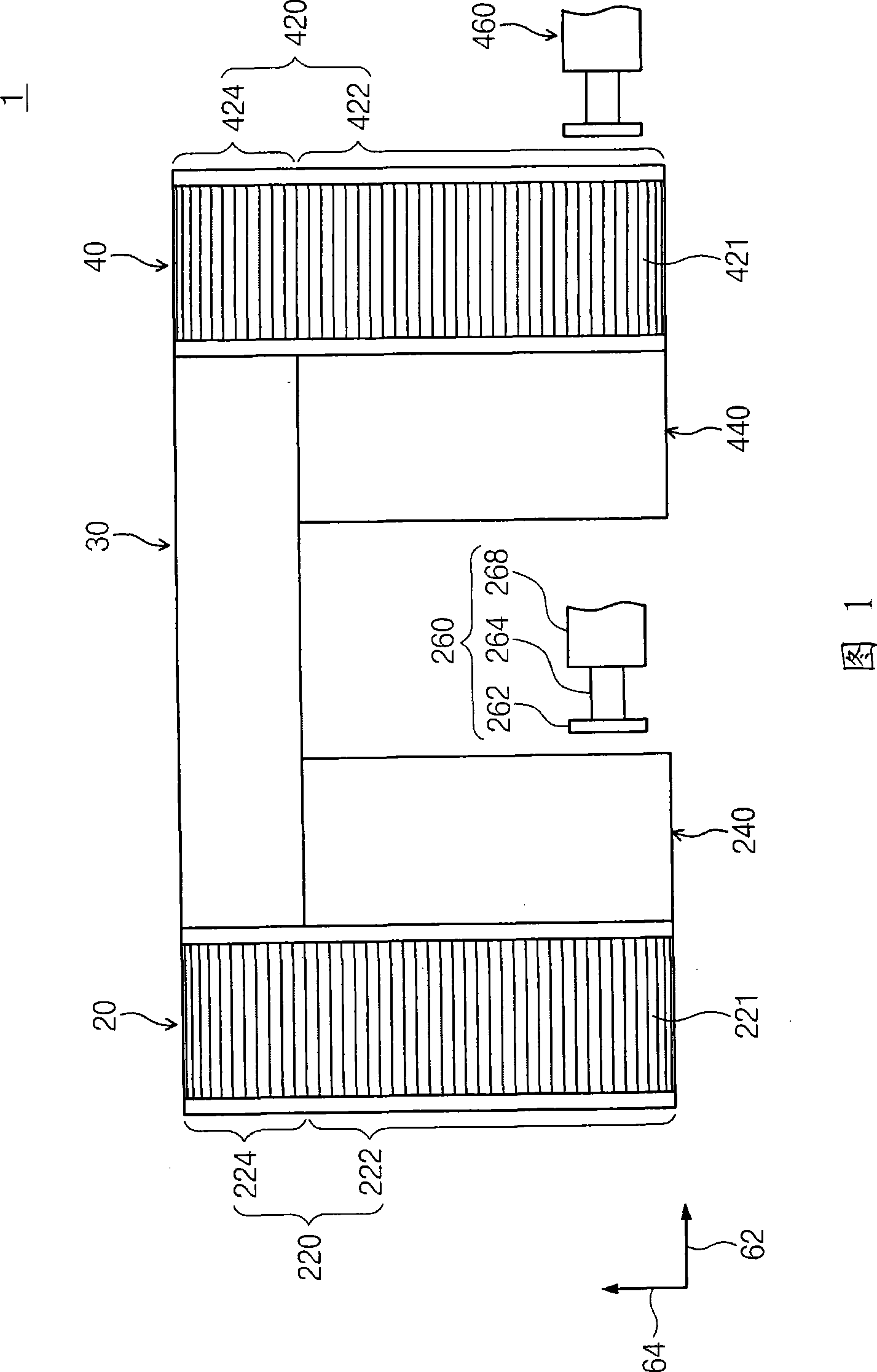
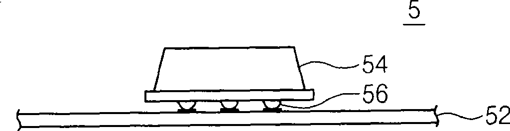
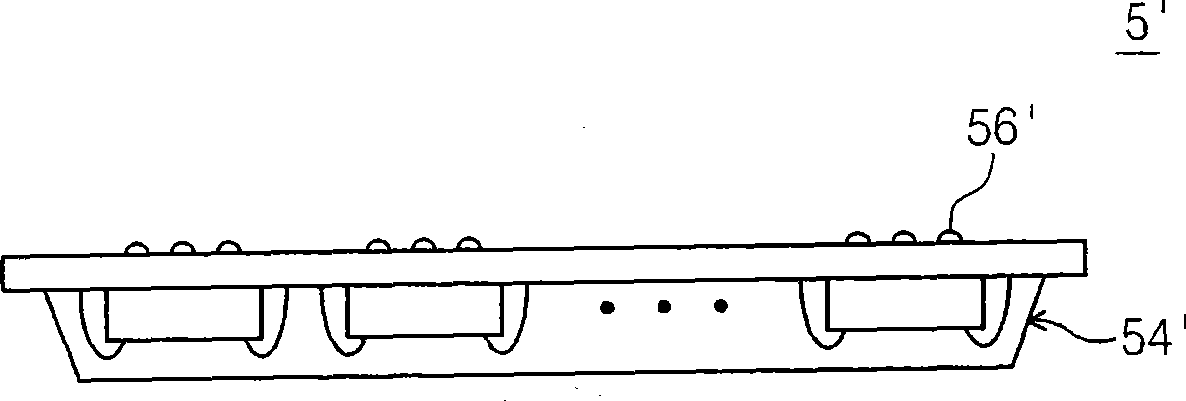
[0026] FIG. 1 is a view schematically illustrating a structure of a reflow device according to an embodiment of the inventive concept. Referring to FIG. 1, the reflow device 1 includes a loader unit 20, a heating unit 30, an unloader unit 40 and a moving unit 50 (shown in Figure 21 middle). The heating unit 30 performs reflow of the external connection terminals (respectively as figure 2 and image 3 Solde...


PUM


Abstract

The invention Provides a reflow apparatus and a method. The reflow apparatus includes a loader unit, a heating unit, an unloader unit, and a moving unit. The loader unit has an input module and an input stacker. Processing objects are stored in vertical stacks in magazines, and a plurality of magazines is stored in the input stacker. The magazines stored in the input stacker are moved to the input module and are introduced into the heating unit by the moving unit. Solder balls provided on the processing objects within the heating unit are quickly processed using an induction heating method. The processing objects that have undergone a reflow process are loaded in a magazine on an output module of the unloader unit and are then stored in an output stacker.

Description

technical field [0001] The inventive concepts disclosed herein relate to a semiconductor manufacturing apparatus and method, and more particularly, to a reflow apparatus and method for reflowing solder balls in a packaging process. Background technique [0002] Semiconductor packaging includes, among other things, the assembly process and the mounting process. The mounting process includes providing and mounting solder balls that function as terminals for electrically connecting the semiconductor chip to an external circuit. The mounting process includes mounting the semiconductor chip provided with the solder balls on a printed circuit board (PCB). Both the assembly process and the mounting process include a reflow step of the solder balls, which is performed by applying heat to the solder balls. The reflow step can take a considerable amount of time, thus reducing the throughput of the packaging process. Therefore, there is still a need for high throughput reflow proces...

Claims


Application Information

Patent Timeline
IPC IPC(8): H01L21/00H01L21/60
CPCH01L2924/0002H05K3/3436B23K2201/40B23K3/0475B23K2101/40H01L2924/00H01L21/67098H01L21/6773
Inventor 金民一丁起权韩一宁
Owner SAMSUNG ELECTRONICS CO LTD
Features
  • R&D
  • Intellectual Property
  • Life Sciences
  • Materials
  • Tech Scout
  • Unparalleled Data Quality
  • Higher Quality Content
  • 60% Fewer Hallucinations
Learn More