Brush electric motor

A motor and crankshaft technology, applied in the direction of electric components, electrical components, electromechanical devices, etc., can solve the problems of toner safety hazards, low life of rotor lead wires, etc., to reduce centrifugal tension, prolong service life, and improve safety factor. Effect

Inactive Publication Date: 2009-06-03
徐荣祖
View PDF0 Cites 7 Cited by
  • Summary
  • Abstract
  • Description
  • Claims
  • Application Information

AI Technical Summary

Problems solved by technology

[0005] The purpose of the present invention is to provide a brushed motor, which solves the potential safety hazard caused by the carbon powder produced when the commonly used brushed motor is running, and at the same time solves the problem of low life of the rotor lead wires due to long-term centrifugal tension

Method used


Image

  • Brush electric motor

Examples


Embodiment Construction

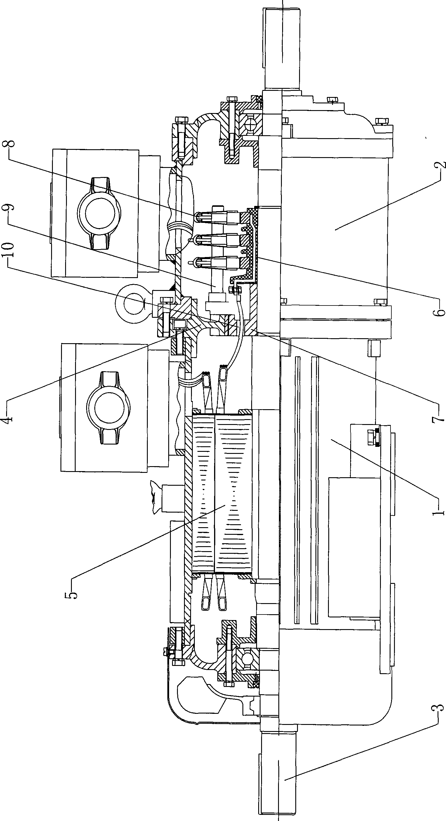
[0022] Such as figure 1 As shown, the brushed motor of the present invention includes a main casing 1, a shaft 3, and a high-end cover 2. The main casing 1 is connected to the high-end cover 2, and an end cover 4 is arranged between the main casing 1 and the high-end cover 2. A brush holder 9 is installed on the end cover 4, and a brush 8 is fixed on the brush holder 9; the shaft 3 is located inside the main casing 1 and the high-end cover 2, and the rotor 5 and the conductive slip ring 6 are fixed on the shaft 3 , the rotor 5 is provided with a rotor lead wire connected to the conductive slip ring 6, and also includes a circular dust-proof fixed plate 7, which is fixed between the rotor 5 on the crankshaft 3 and the conductive slip ring 6, and the rotor lead wire passes through Pass the dust-shielding fixed plate 7, and the dust-shielding fixed plate 7 is provided with a sealing ring 10 to seal the rotor lead wire; the dust-shielding fixed plate 7 corresponds to the end cover...


PUM


Abstract

A brush electric motor comprises a main case, a crankshaft and a high end cover, wherein, the main case is connected with the high end cover, an end cover is arranged between the main case and the high end cover, the crankshaft is positioned inside the main case and the high end cover and is fixed with a rotor and an electric conduction slide ring, and the rotor is provided with a rotor lead wire which is connected with the electric conduction slide ring. The brush electric motor has the main design that a round dust blocking fixed plate is fixed between the rotor and the electric conduction slide ring on the crankshaft, and the rotor lead wire passes through the dust blocking fixed plate; furthermore, the dust blocking fixed plate is corresponding to the end cover by adopting clearance fit. Due to the design of the dust blocking fixed plate, carbon powder granules produced by brush friction can be effectively prevented from entering between a stator and a rotor, and the safety factor of the work environment inside the electric motor can be improved; meanwhile, the rotor lead wire can be fixed and buffered, so that the centrifugal tension applied on the rotor lead wire can be reduced when the electric motor runs at high speed, and the service life thereof can be prolonged.

Description

technical field [0001] The invention relates to a motor with a brush, in particular to a motor with a brush provided with dust blocking and fixing devices. Background technique [0002] At present, the brushes (conductive slip rings and collector rings) of brushed motors commonly used are mostly made of carbon conductive materials, which will produce a lot of tiny carbon powder after long-term friction. However, there is no isolation device between the brush chamber and the rotor of most brushed motors, so part of the carbon powder generated will fall between the stator and the rotor as the motor runs. If it accumulates too much, the stator and rotor will be damaged. conduction, causing a safety hazard. [0003] At the same time, the rotor of the commonly used brushed motor and the conductive slip ring are connected by rotor lead wires. With the high-speed operation of the rotor, a large centrifugal force will be generated on the rotor lead wires, which also keeps the rotor...

Claims


Application Information

Patent Timeline
Patent Type & Authority Applications(China)
IPC IPC(8): H02K5/04H02K5/14H02K9/26
Inventor 徐荣祖
Owner 徐荣祖
Why Eureka
Try Eureka