Method and device for setting and activating a hydrodynamic retarder of a motor vehicle

A technology of hydraulic reducer and reducer, which is applied in the direction of hydraulic brake, brake type, mechanical equipment, etc., can solve the problems of high cost and structural expenditure, and achieve the effect of improving accuracy and adjusting accuracy

Inactive Publication Date: 2009-06-03
ZF FRIEDRICHSHAFEN AG
View PDF6 Cites 11 Cited by
  • Summary
  • Abstract
  • Description
  • Claims
  • Application Information

AI Technical Summary

Problems solved by technology

[0016] A disadvantage of the pneumatic retarder control system is the comparatively high costs and structu...

Method used


Image

  • Method and device for setting and activating a hydrodynamic retarder of a motor vehicle
  • Method and device for setting and activating a hydrodynamic retarder of a motor vehicle

Examples


Embodiment Construction

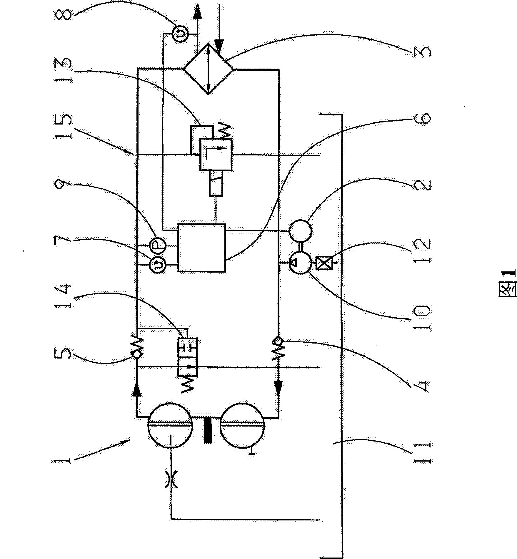
[0049] FIG. 1 shows a vehicle retarder circuit 15 formed as a working circuit of the hydrodynamic retarder 1 . The structure and operating principle of such gear units are well known, so that only the components relevant to the invention will be discussed in detail here.

[0050] The working circuit 15 has a pump 10 and an upstream filter 12 for oil supply, the pump 10 can be driven and adjusted by the electric motor 2 . The pump 10 may be supplied with oil from an oil pan 11 . Furthermore, a heat exchanger 3 is provided for dissipating the kinetic energy of the flow converted into heat in the gear unit 1 . For filling and emptying the gear unit 1, two non-return valves 4, 5 are arranged on the inlet or outlet side, wherein an emptying valve 14 is additionally arranged on the gear unit outlet, via which the The gear unit 1 can be completely emptied.

[0051] The working circuit 15 can be adjusted by the control and regulation unit 6 . The control and regulation unit 6 is c...


PUM


Abstract

The invention relates to a method for setting and activating a hydrodynamic retarder (1) of a motor vehicle, in which method the retarder (1) has a regulable hydraulic circuit (15) and means for measuring the hydraulic pressure in the hydraulic circuit (15), and in which method at least one pre-setting takes place in order to generate a braking torque which follows a predefined brake moment characteristic curve which is permanently stored in a control and regulating unit (6) and by means of which the retarder (1) is activated in driving operation. In order to improve the setting accuracy of the braking torque of said retarder, it is provided that the hydraulic pressure in the hydraulic circuit (15) of the retarder (1) is taken into consideration at least during the pre-setting. Additionally provided is a device in which the retarder (1) has a regulable hydraulic circuit (15) with at least one pressure sensor (9), and in which the hydraulic circuit (15) is assigned a control and regulating unit (8) which has a non-volatile data memory and a processor unit in which current input data and stored data can be processed, and in which an output signal for activating an electric valve device (13) and/or an oil filling device of the retarder (1), by means of which a predetermined nominal braking torque (Msoll) can be set, can be generated from the processed data.

Description

technical field [0001] The invention relates to a method and a device for regulating and controlling a hydrodynamic retarder of a motor vehicle according to claim 1 or the preamble of claim 17 . Background technique [0002] Hydrodynamic retarders are used in motor vehicles, preferably trucks, as an additional wear-free permanent braking device to relieve the wheel brakes, which are usually designed as friction brakes. The retarder reduces wear and prevents friction brakes from overheating, for example during braking from high speeds, in vehicles with a high gross weight and in the case of longer downhill driving. In addition, braking comfort (e.g. constant maintenance of speed on slopes) can also be increased by coordinated braking. [0003] In a hydraulic reducer, the mechanical energy of the transmission shaft is converted into the kinetic energy of the liquid (usually oil), wherein the physical working principle is consistent with a hydraulic clutch, which has a pump wh...

Claims


Application Information

Patent Timeline
IPC IPC(8): B60T10/02
CPCB60T10/02
Inventor 伯恩哈特·格鲁普伯恩哈德·赖施路哲尔·龙格弗兰克·索特彼得·施米特纳
Owner ZF FRIEDRICHSHAFEN AG
Why Eureka
Try Eureka