Display device and its manufacturing method, pattern displaying method, and blind device and blind method

A technology for a display device and a manufacturing method, which is applied in the direction of display devices, lighting devices, instruments, etc., can solve the problems of complex electrode wiring patterns, lower value, and inability to see through the background, and achieve good display effects and decoration, simple structure, and Improve the effect of the display effect

Inactive Publication Date: 2009-06-03
THE FUJIKURA CABLE WORKS LTD
View PDF3 Cites 25 Cited by
  • Summary
  • Abstract
  • Description
  • Claims
  • Application Information

AI Technical Summary

Problems solved by technology

[0010] However, when the area of ​​the display part, which is the opaque part, is large, the background cannot be seen through, and the transparency which is a characteristic of the display device is lost, thereby reducing its value.
[0011] In a display device in which LED elements are placed between transparent glass plates, only the LED elements block the transmitted light, so the transparency is better than the above-mentioned devices, but the electrode wiring pattern becomes complicated, resulting in very difficult manufacturing. difficult and expensive
[0012] In addition, unlike a display device in which a light source and a light guide plate are provided separately, in order to change the appearance of the display part, it is necessary to replace the entire unit including the light source (LED element).

Method used


Image

  • Display device and its manufacturing method, pattern displaying method, and blind device and blind method
  • Display device and its manufacturing method, pattern displaying method, and blind device and blind method
  • Display device and its manufacturing method, pattern displaying method, and blind device and blind method

Examples


Embodiment Construction

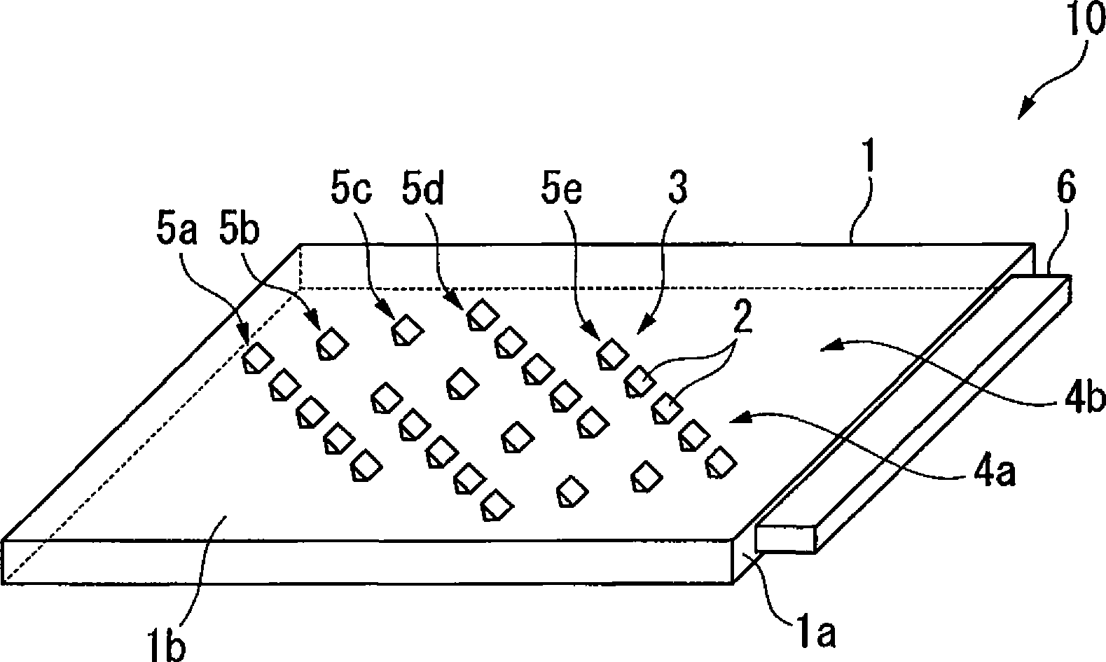
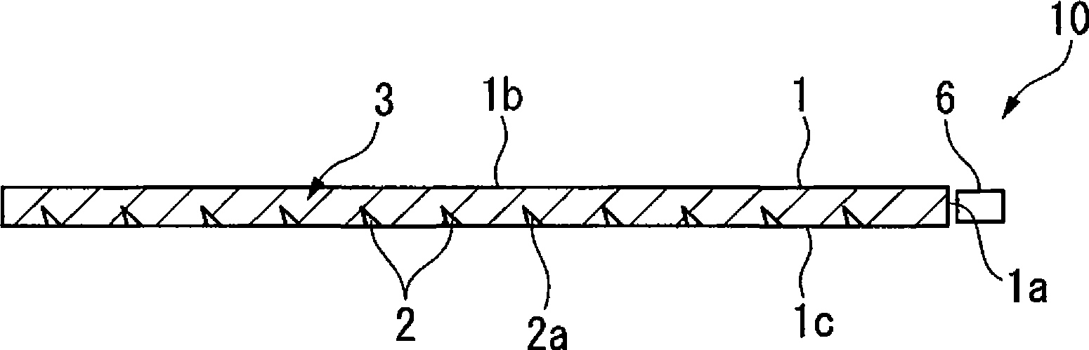
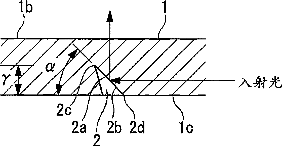
[0077] Figure 1 to Figure 4 It is a figure which shows the display device 10 which is the 1st example of the display device of this invention. figure 1 is a perspective view schematically showing the display device 10 of the present invention, figure 2 is a cross-sectional view of the display device 10, image 3 is an enlarged sectional view of a main part of the display device 10, Figure 4 It is a plan view of the dot reflector 2 .

[0078] The display device 10 includes a light guide plate 1 and a light source 6 provided on an end surface 1 a of the light guide plate 1 .

[0079] As the light source 6, an LED, an LD (Laser Diode), or the like can be used. The light source 6 is preferably formed extending along the extending direction of the light guide plate 1 . In the illustrated example, the light source 6 is formed to extend along one end surface 1 a of the substantially rectangular light guide plate 1 .

[0080] As the light source 6, for example, a member in wh...


PUM

PropertyMeasurementUnit
surface roughnessaaaaaaaaaa

Abstract

This display device (10) is comprised of a light guide plate (1) and a light source (6) provided on an end surface (1a) side of the light guide plate (1). A display unit (3) provided with a dot-like reflecting unit (2) with a reflective surface (2a) for reflecting light projected from the light source (6) to a surface (1b) side is formed on the light guide plate (1). The display unit (3) is set for the reflecting light from the dot-like reflecting unit (2) to be visually recognizable. The display device (10) is good at transparency and readily visually recognized, and can be easily manufactured at a low cost.

Description

technical field [0001] The present invention relates to a display device used for a display or the like, a method of manufacturing the same, a pattern display method using the display device, and a shielding device and a shielding method using the display device. [0002] This application claims priority based on Japanese Patent Application No. 2006-117238 filed in Japan on April 20, 2006 and Japanese Patent Application No. 2007-052910 filed in Japan on March 2, 2007, and uses the contents thereof. Background technique [0003] In recent years, opportunities for LEDs (light-emitting diodes) to be used in various applications as high-efficiency, long-life light sources are increasing. [0004] LED is a directional point light source. Since its use as spot lighting alone is limited, it is mostly used in combination with light guide plates such as transparent resin plates as a linear or planar light source. For example, LCD backlights, advertising light panels, etc. [0005] ...

Claims


Application Information

Patent Timeline
Patent Type & Authority Applications(China)
IPC IPC(8): G09F13/18G02F1/13357F21V8/00F21Y101/02G02B6/00
Inventor 上片野充妻沼孝司鹿岛孝文
Owner THE FUJIKURA CABLE WORKS LTD
Why Eureka
Try Eureka