
DME fuel filling system

A fuel and fuel tank technology, applied in the field of DME fuel filling system, can solve the problems of shortening and not fully achieving DME fuel filling time, etc.

Inactive Publication Date: 2009-06-10
CENTRAL MOTOR WHEEL CO LTD
View PDF6 Cites 0 Cited by
  • Summary
  • Abstract
  • Description
  • Claims
  • Application Information

AI Technical Summary

Problems solved by technology

Therefore, the shortening of the charging time required for DME fuel cannot be sufficiently achieved.

Method used


Image

  • DME fuel filling system
  • DME fuel filling system
  • DME fuel filling system

Examples


Embodiment 1~3

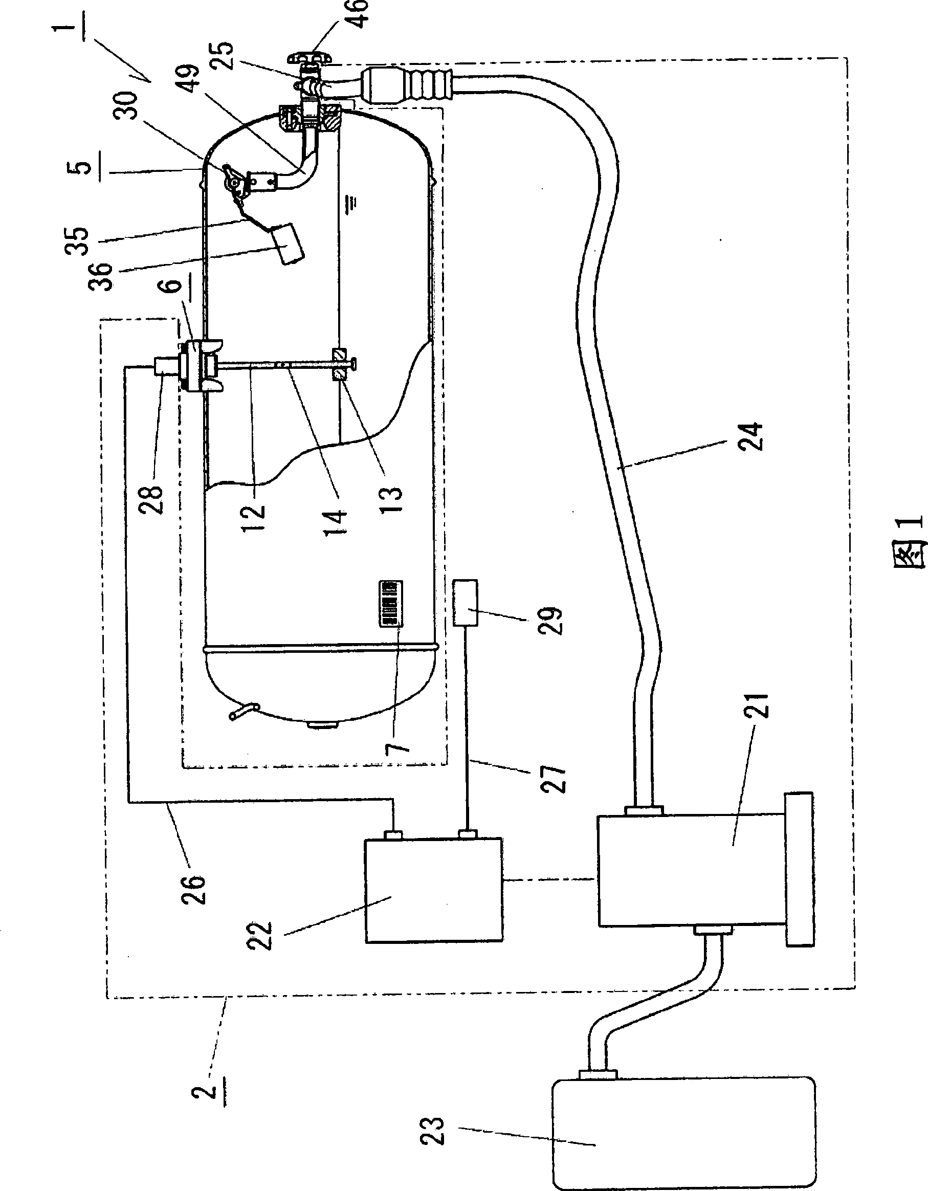
[0070] In Embodiments 1 and 2, as shown in FIGS. 1 and 6, DME fuel filling systems 1, 51 are equipped with fuel filling devices 2, 52 for filling DME fuel into fuel tanks 5, 55 arranged horizontally on automobiles. . At this time, the fuel charging control device 2, 52 is usually arranged at a DME fuel supply station. In Embodiment 3, like Embodiments 1 and 2, it is a DME fuel filling system provided with a horizontal fuel tank and a fuel filling control device.

Embodiment 1

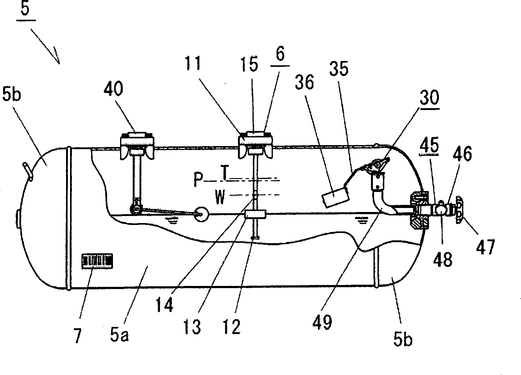
[0072] For example, as a fuel tank 5 arranged horizontally on a truck, such as figure 2 As shown, it consists of a cylindrical tube part 5a and hemispherical tube cover parts 5b, 5b joined to openings on both sides of the tube part 5a. This fuel tank 5 is fixed on the vehicle by a fixing member (not shown), and a valve device equipped with a filling valve 46 and a filling valve opening and closing handle 47 for opening and closing the filling valve 46 is arranged on one of the cylinder cover parts 5b. 45. And, on this filling valve 46, be provided with the fast coupling device 48 (quick-coupling) of detachable later-mentioned filling nozzle 25, when filling DME fuel, install filling nozzle 25 on the quick coupling device 48 and Fill up with fuel.

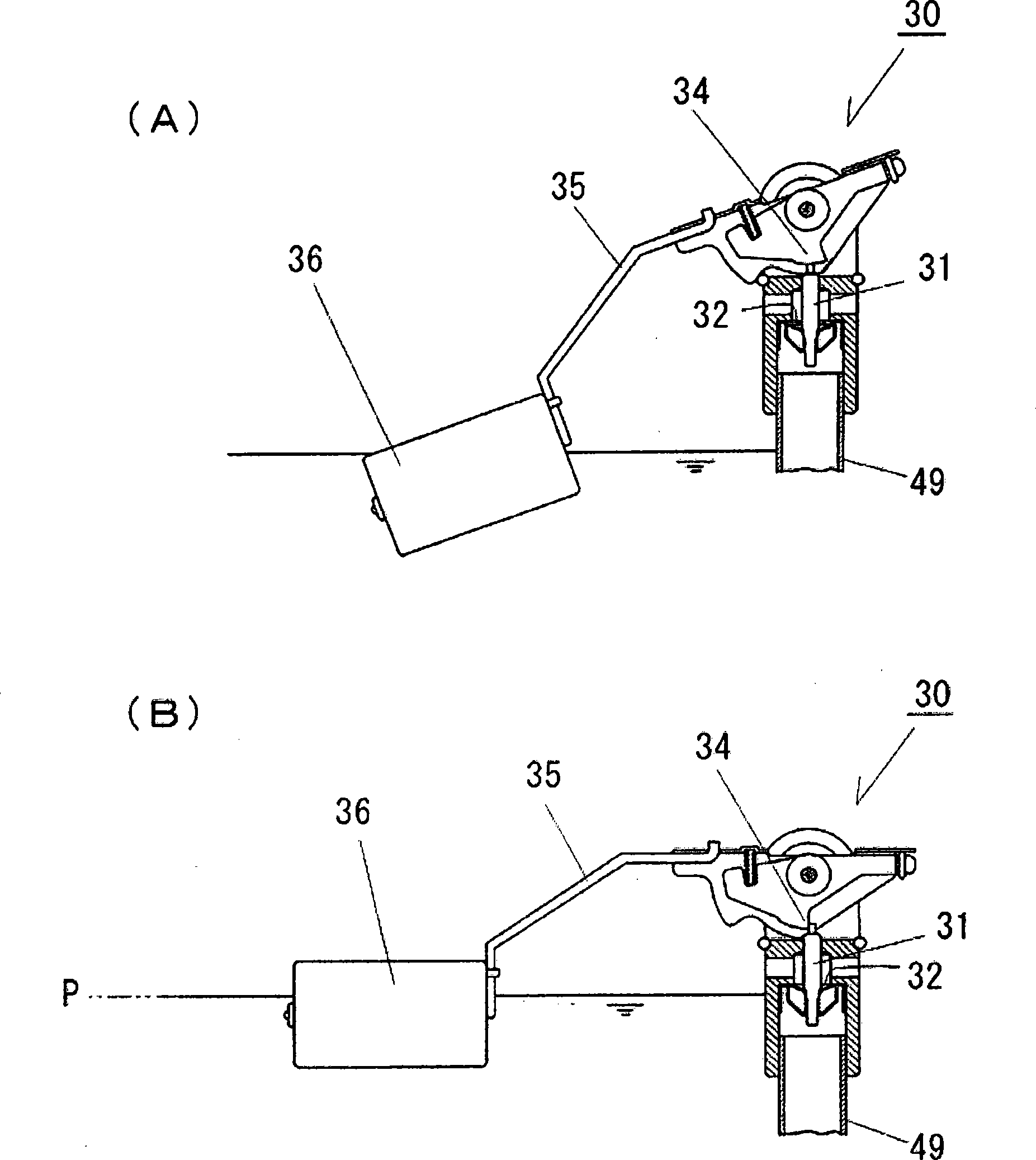
[0073] Furthermore, in the fuel tank 5, a gas filling pipe 49 communicating with the above-mentioned filling valve 46 is arranged. Furthermore, the gas filling pipe 49 has its front end provided at the upper portion inside the fu...

Embodiment 2

[0110]In the structure of Embodiment 2, as shown in FIG. 6 , the structure is as follows: the fuel tank 55 is not provided with the overfill prevention device 30 of Embodiment 1, the liquid level detection device 56 is equipped with a deceleration position switch 14, and if it reaches the maximum filling amount, it can be displayed. The maximum liquid height P of the maximum liquid level is then according to the maximum position switch 64 of the ON action of the float 13 . That is, when the DME fuel is filled, the liquid level rises, and if it reaches the maximum liquid level P, the buoy 13 makes the maximum position switch 64 ON. Acquired by the filling control device 22.

[0111] Furthermore, the filling control device 22 has filling stop control processing contents such as obtaining the liquid level information indicating the ON operation of the maximum position switch 64 from the above-mentioned liquid level detection device 56 and driving and stopping the fuel filling mac...


PUM


Abstract

The present invention proposes a DME fuel filling system capable of restraining water impact generated because of variation of filling speed and at same time of shortening filling time when filling DME fuel into a fuel pot. The invention comprises: acquiring container information from a container recognition mechanism arranged on a fuel pot (5); setting limit liquid height (T) and speed reduction liquid height (W); calculating control liquid volume from the limit liquid height (T) to the speed reduction liquid height (W); acquiring liquid height information acquired with a liquid height detection mechanism arranged in the pot (5); filling fuel in high speed until the speed reduction height (W); reducing speed from the high filling speed based on control liquid volume until the limit liquid height (T); driving to control a fuel filling machine (21). The invention may adequately reduce filling speed unit max filling volume and adequately restrains water impact caused by filling stop. Further, the filling period for max filling volume may shorten as much as possible.

Description

technical field [0001] The invention relates to a DME fuel filling system for filling a fuel tank storing DME fuel with DME fuel. Background technique [0002] For example, in recent years, with the strict control of exhaust gas emissions from automobiles and other vehicles, vehicles using liquefied gas fuel for the purpose of low pollution tend to increase. Liquefied petroleum gas (hereinafter referred to as LPG) fuel is generally known as this liquefied gas fuel, but dimethyl ether (hereinafter referred to as DME) fuel is also being paid attention to as diesel alternative to diesel engines. This DME fuel has the advantage of being able to reduce the emission of PM and NOx to an extremely small amount compared with diesel oil, and it is also highly expected as a low-pollution measure. [0003] However, in the fuel tanks storing the above-mentioned LPG fuel or DME fuel, it is known that the maximum filling amount of the fuel filled in the fuel tank is regulated, and it is k...

Claims


Application Information

Patent Timeline
Patent Type & Authority Applications(China)
IPC IPC(8): B67D5/02B67D5/08B67D5/30B67D7/02B67D99/00
CPCB60S5/02F17C5/02F17C13/021F17C2205/0302F17C2227/04
Inventor 岩月惠司稻垣秀幸
Owner CENTRAL MOTOR WHEEL CO LTD
Learn More