
Electric voltage temporary drop detecting method and apparatus

A technology of voltage sag and detection method, which is applied in the field of electric power and can solve problems such as large voltage sag errors

Inactive Publication Date: 2009-06-10
STATE GRID BEIJING ELECTRIC POWER +1
View PDF0 Cites 20 Cited by
  • Summary
  • Abstract
  • Description
  • Claims
  • Application Information

AI Technical Summary

Problems solved by technology

[0006] The present invention aims to provide a method and device for detecting voltage sags, which can solve the problem of large errors in detecting voltage sags using the product algorithm of two sampled values

Method used

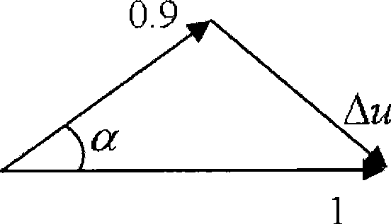
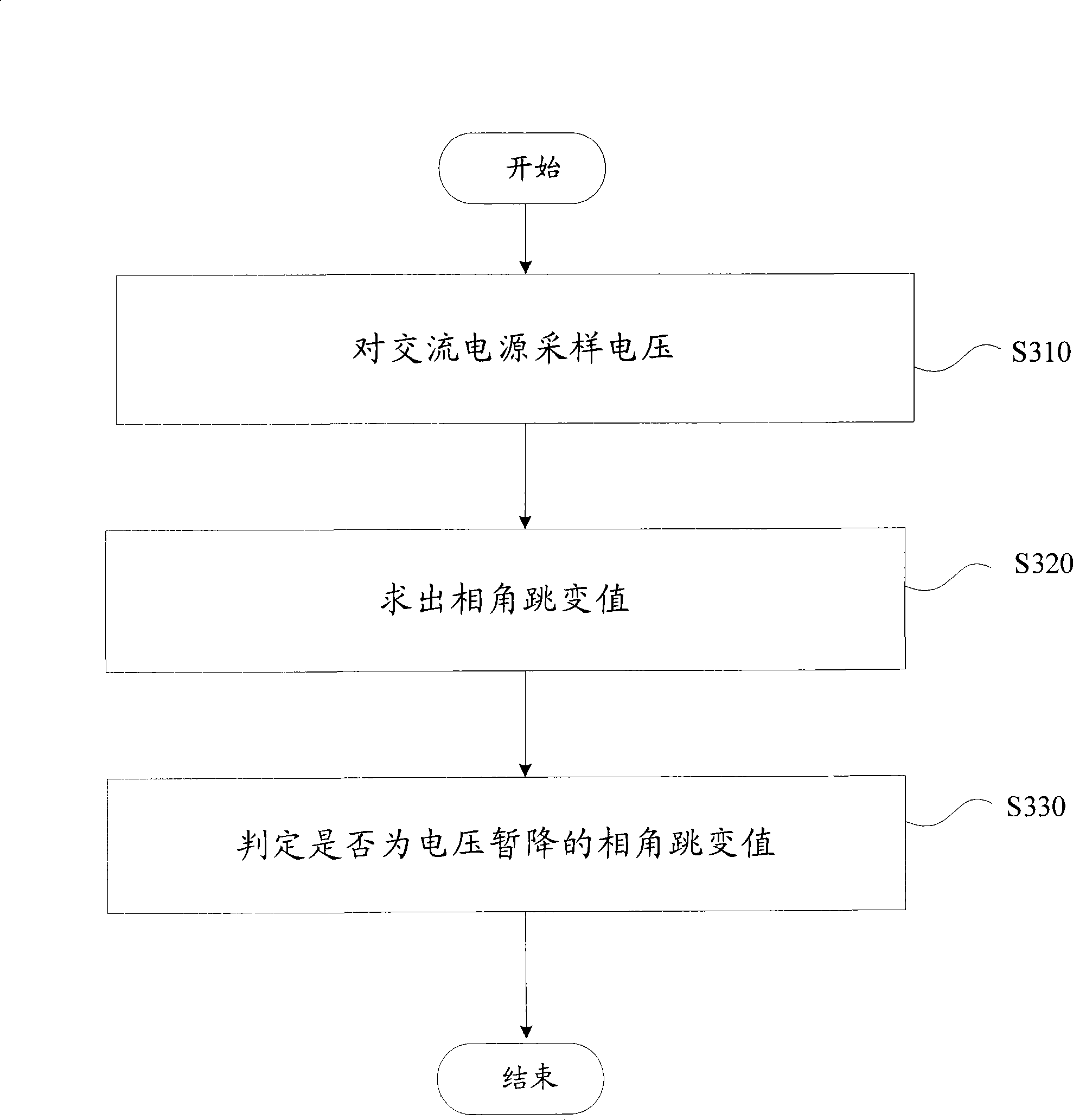

Image

  • Electric voltage temporary drop detecting method and apparatus
  • Electric voltage temporary drop detecting method and apparatus
  • Electric voltage temporary drop detecting method and apparatus

Examples


Embodiment Construction

[0054] The present invention will be described in detail below with reference to the accompanying drawings and in combination with embodiments.

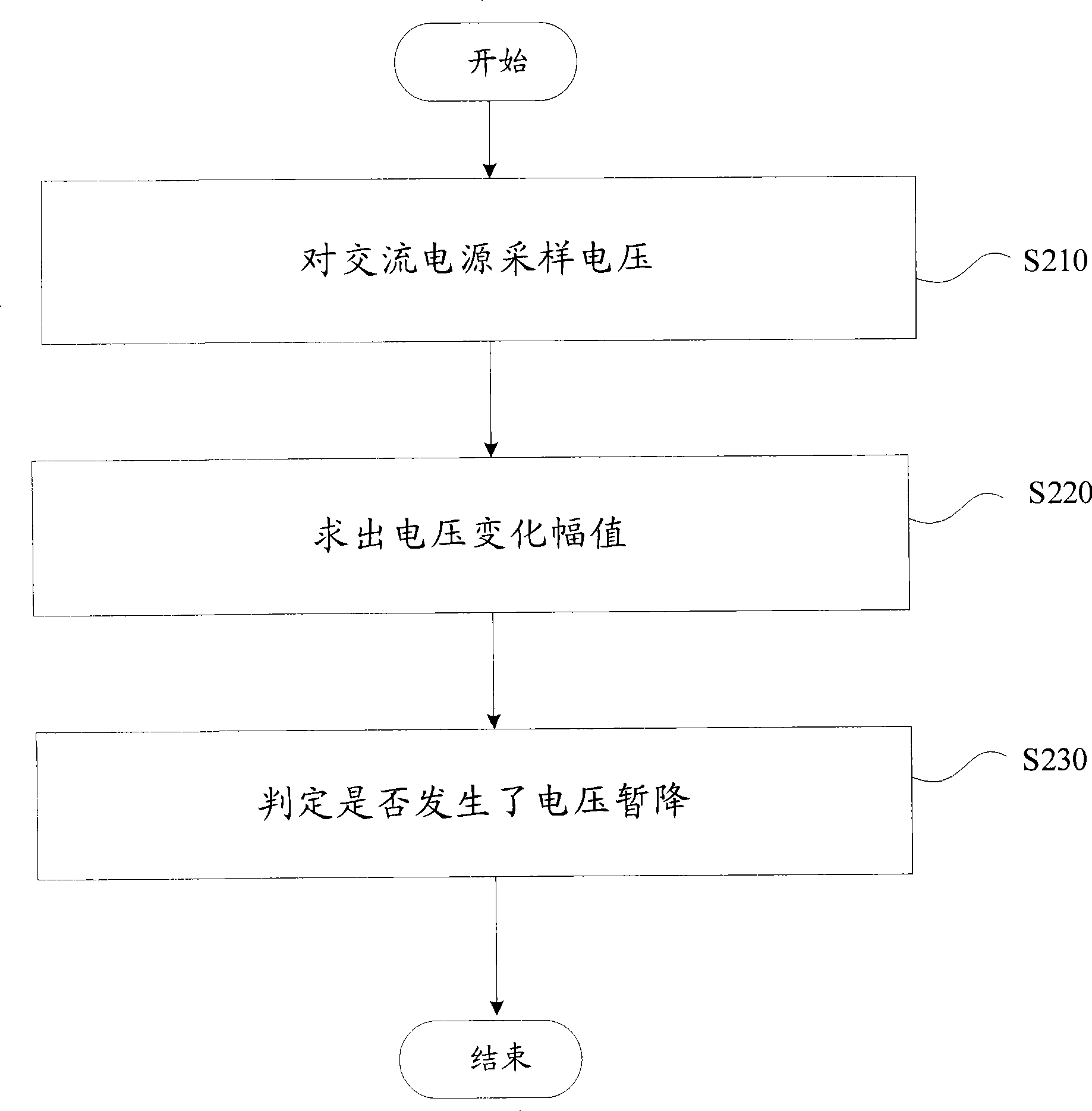
[0055] figure 2 A flow chart showing a voltage sag detection method according to an embodiment of the present invention includes the following steps:

[0056] Step S210, for AC power at time t1 and t 2 Sampling voltage, get u respectively 1 and u 2 , where, the normal power supply voltage u=U sin(ωt+φ)(11) of the AC power supply, in (11) formula, U is the voltage amplitude constant, ω is the angular velocity constant of the voltage change, t is the time variable, φ is the phase; t1 and t 2 The time interval between is ΔT;

[0057] In step S220, combine the following equations (12) to (15) to obtain the variation amplitude ΔU:

[0058] u 1 =U 1 sin(ωt+φ) (12)

[0059] u 2 =U 2 sin(ωt+φ) (13)

[0060] u 1 -u 2 =(U 1 -U 2 )sin(ωt+φ) (14)

[0061] ΔU=U 1 -U 2 (15)

[0062] Step S230, judging whether ΔU...


PUM


Abstract

The invention provides a voltage dip testing method, comprising the steps of: a) sampling voltage on AC power at the moment t1 and t2, respectively obtaining u1 and u2, wherein normal supply voltage u of the AC power is equal to U sine(omega t + phi); b) obtaining changing amplitude delta U; c) judging whether delta U > |delta u|, if true, voltage dip happens, wherein delta u is the presupposed allowable voltage dip value. The invention also provides a voltage dip testing device. The invention accurately judges the voltage dip, and accurately computes phase jump angle of the voltage dip.

Description

technical field [0001] The present invention relates to the field of electric power, in particular to a voltage sag detection method and device. Background technique [0002] With the development of modern science and technology, more and more industrial production processes and assembly lines (such as semiconductor manufacturing, computer integrated manufacturing, paper industry, etc.) Several cycles of power interruption or voltage sag will affect the normal operation of these devices. Therefore, high-quality power supply has become the basic condition for normal production and life in modern society. At present, in the study of power quality problems, voltage sag has been considered as a very serious dynamic power quality problem that affects the normal and safe operation of many electrical equipment. [0003] Considering the randomness and rapidity of voltage sag, in order to make the dynamic power quality adjustment device have a good real-time control effect, the fir...

Claims


Application Information

Patent Timeline
IPC IPC(8): G01R19/00G01R19/165
Inventor 赵小英罗湘蒋晓春李奇睿刘亚萍
Owner STATE GRID BEIJING ELECTRIC POWER
Learn More