Deep dehydrating method and device for oil product

A technology for deep dehydration and oil products, which is applied in the direction of hydrocarbon oil dehydration/demulsification, grease/oily substance/suspton removal device, mechanical dehydration/demulsification, etc., which can solve the problem of large operating pressure drop, short service life, Energy consumption and complex operation

Active Publication Date: 2014-08-13
EAST CHINA UNIV OF SCI & TECH
View PDF8 Cites 37 Cited by
  • Summary
  • Abstract
  • Description
  • Claims
  • Application Information

AI Technical Summary

Problems solved by technology

For gravity sedimentation, it can mainly remove clear water in oil products, that is, free water droplets with a particle size greater than 100 μm, and can not effectively separate and remove dispersed water droplets below 100 μm; cyclone separation technology is suitable for rapid removal of large amounts of water. Water droplets below 15 μm and emulsified water droplets cannot be effectively separated, because the potential energy needs to be converted into rotational kinetic energy for separation, and the energy consumption is relatively high; coalescing filtration is separated by permeability, and the scope of application is narrow, and there is a short service life in the factory application process However, the use of salt adsorption, electric field separation, and flash separation is relatively energy-consuming and complex in operation, and is only suitable for specific treatment media
[0004] The patent ZL01823742.8 oil dehydrator discloses a method of dehydrating oil by using a membrane, but there are problems of high cost of use and easy pollution and damage; the patent application number 200810042145.2 discloses a method and device for

Method used

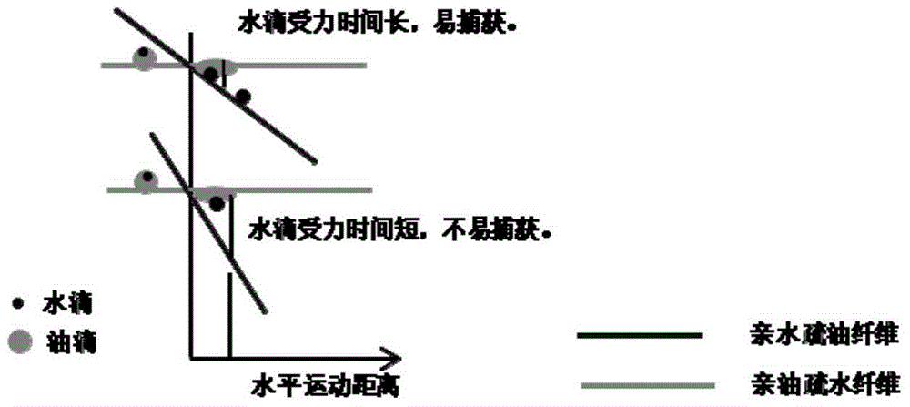
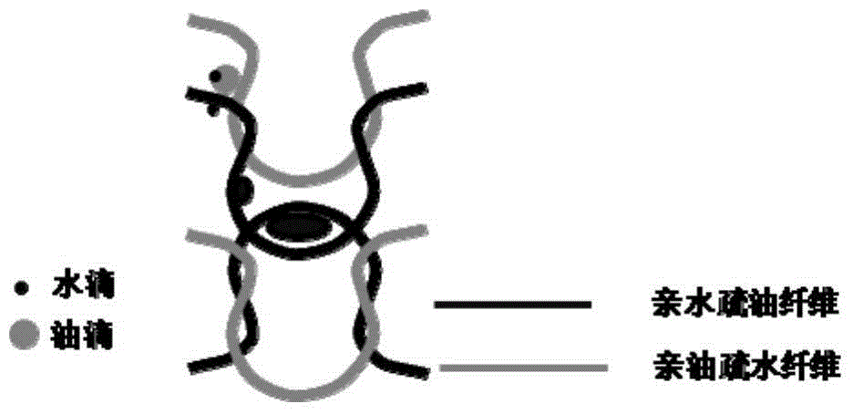
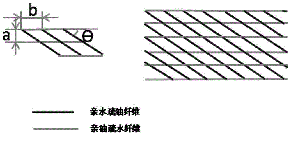

Image

  • Deep dehydrating method and device for oil product
  • Deep dehydrating method and device for oil product
  • Deep dehydrating method and device for oil product

Examples


Embodiment

[0039] Two sets of diesel hydrogenation units in a petrochemical company adopted the method and device for deep dehydration of oil products of the present invention to dehydrate the diesel oil from the fractionation tower of the diesel hydrogenation unit, and the dehydrated diesel oil was sent to the finished oil tank.

[0040] The schematic diagram of the above-mentioned device is shown in Figure 6 As shown, it includes housing 1, oil inlet 2, fluid rectifier 3, X-shaped braided layer 4 (fiber coalescence separation layer), corrugated reinforced separation layer 5, Ω-shaped braided layer 6 (fiber coalescing supplementary layer), Water bag 10 and purified oil phase outlet 7;

[0041] Wherein, the oil inlet 2 is at one end of the upper part of the housing 1, and the purified oil phase outlet 7 is at the other end of the upper part of the housing 1; the water bag 10 is at the bottom of the housing 1, and the water bag 10 is opposite to or slightly Relatively arranged with devi...


PUM


Abstract

The invention relates to a deep dehydrating method and device for an oil product. The deep dehydrating method for the oil product comprises the steps of firstly, enabling the oil product with trace water to pass through a rectifier to ensure that a fluid is uniform; secondly, realizing the capture, agglomeration and growth of trace water drops and demulsification and separation of a trace water-in-oil emulsion through one or more segments of X-shaped oleophylic/lyophobic and hydrophilic/oleophobic fiber braid layers; next, realizing the rapid agglomeration, growth and separation of the water drops through microwave-forced settlement separation; finally, realizing the capture and separation of the extremely trace water drops in the oil product through one segment of omega-shaped oleophylic/lyophobic and hydrophilic/oleophobic fiber braid layer, thereby realizing the deep dehydration of the oil product. The invention also provides a set of device for realizing the method. The device comprises a shell, a feeding pipe, a rectifier, a fiber agglomeration layer, a microwave forced separation layer, a liquid level meter and other parts. The method is high in separation efficiency, low in energy consumption and long in continuous operation period, and can be widely applied to the deep dehydrating processes of all oil products with trace water.

Description

technical field [0001] The invention belongs to the field of petrochemical oil dehydration, and in particular relates to a method and device for deep dehydration of oil. Background technique [0002] Water content in oil has a major impact on the safe use of petrochemical production equipment and subsequent refined oil in engines. For example, water content in crude oil will increase the transportation volume, and more importantly, it will bring difficulties to crude oil processing, increasing atmospheric and vacuum distillation. The energy consumption of the device. Because the relative molecular energy of water is much smaller than that of oil, the volume increases sharply after gasification, which increases the pressure drop of the system and the power consumption increases accordingly. Therefore, if the water content in the oil is high, the operation of the device will fluctuate, causing Punch tower. Moreover, the inorganic salts (Call2, MgCl2) brought in by water will...

Claims


Application Information

Patent Timeline
IPC IPC(8): C10G33/06
CPCC02F1/40C10G33/00C10G33/06Y02W10/37
Inventor 杨强卢浩许萧王朝阳杨森
Owner EAST CHINA UNIV OF SCI & TECH
Why Eureka
Try Eureka