Basic electric parameter static measurement method for three phase permanent magnet synchronous machine

A permanent magnet synchronous motor, electrical parameter technology, applied in the direction of motor generator testing, measuring devices, measuring electrical variables, etc., can solve problems such as noise and inconvenience, and achieve the effect of avoiding noise problems, simplifying costs and procedures

Active Publication Date: 2009-06-10
DELTA ELECTRONICS INC
View PDF0 Cites 24 Cited by
  • Summary
  • Abstract
  • Description
  • Claims
  • Application Information

AI Technical Summary

Problems solved by technology

However, the existing method for measuring the basic electrical parameters of permanent magnet synchronous motors is to use the prime mover to drive the motor under test, that is, to make the motor under test form a generator mode, and to add a load to its output. When the prime mover reaches a steady state, by The short-circuit test obtains the voltage an

Method used


Image

  • Basic electric parameter static measurement method for three phase permanent magnet synchronous machine
  • Basic electric parameter static measurement method for three phase permanent magnet synchronous machine
  • Basic electric parameter static measurement method for three phase permanent magnet synchronous machine

Examples


Embodiment Construction

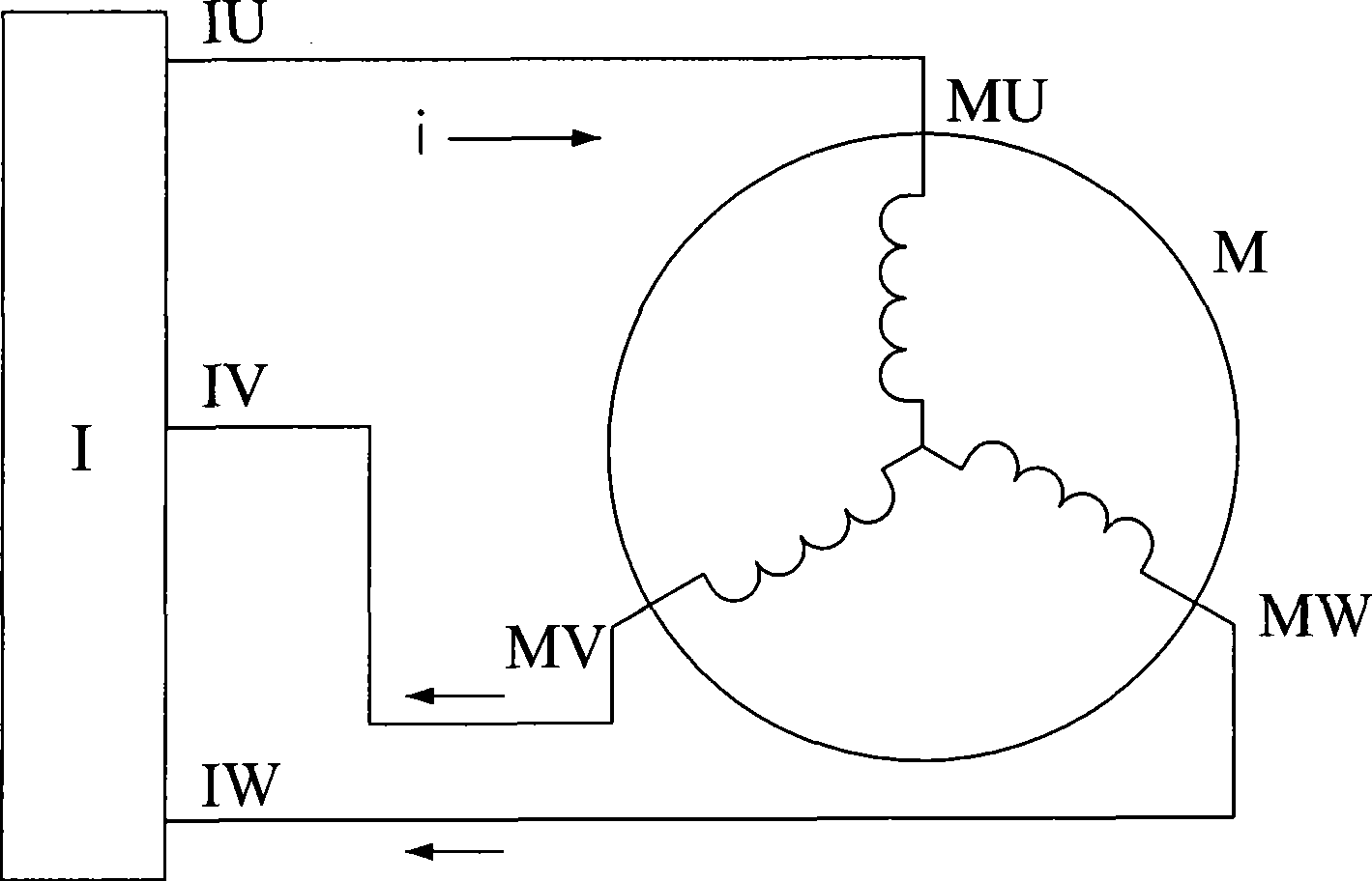
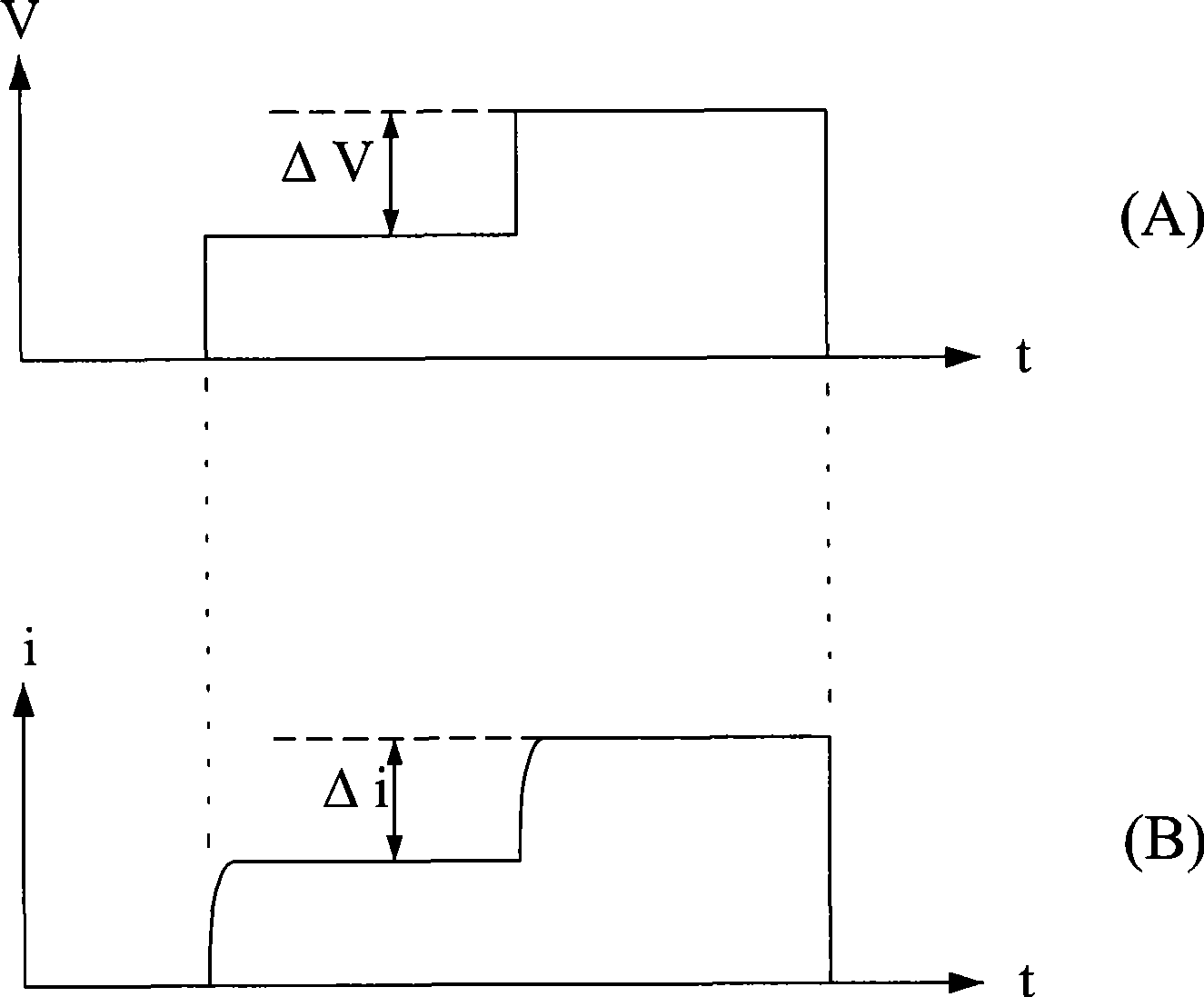
[0033] The basic electrical parameters of a rotating electrical machine are mainly motor resistance and motor inductance. The measurement of the present invention is divided into two stages, the first stage is to measure the motor resistance, and the second stage is to measure the motor inductance. see figure 1 , which is a system architecture diagram of the present invention when measuring motor resistance, for connecting the three power supply input terminals MU, MV and MW of the three-phase permanent magnet synchronous motor M to be tested to the output terminals IU, IV and IW of the frequency converter I respectively , to control the output voltage of the frequency converter I so that it can achieve the DC voltage input function, and lock the rotating shaft (not shown) of the motor M to be tested with a mechanical brake (not shown) so that it cannot run, please refer to Figure 5 , the left half of which shows the measurement process of the motor resistance. Firstly, the i...


PUM


Abstract

The present invention provides a static measuring method of basic electric parameter of three-phase permanent magnet synchronous motor. In a state that a rotating shaft is fixed, the rated current value of machine to be tested and 150% of the rated current value are respectively input. The corresponding voltage value of V100and V150are recorded. The quotient obtained through dividing the voltage difference to the current difference is the resistance value of motor. The electric period is divided into six voltage vectors in the vector control state. Each electric vector is executed with a voltage circulation. One quarter of V150% is output with step mode. V150% is output when the current is stable. Then a stable current is waited. The steps are repeated for four cycles. Then voltage vector is alternated and the voltage circulation is repeated until all the voltage vectors are completed. Finally the rising times of each vector are compared and converted to an inductance. The greatest value is defined to q-axis inductance. The least value is defined to d-axis inductance.

Description

technical field [0001] The invention relates to a three-phase permanent magnet synchronous motor, in particular to the measurement of electrical parameters of this type of motor. Background technique [0002] With the advancement of science and technology, rotating electrical machines have made considerable progress, especially since the advent of high-energy permanent magnets, which has enabled the realization of high-efficiency permanent magnet motors and their applications have become more extensive. The basic electrical parameters of the rotating electrical machine, such as resistance and inductance, are the performance of the basic characteristics of the rotating electrical machine, and the correct basic parameter values ​​must be obtained before the most effective control and use of the electrical machine. However, the existing method for measuring the basic electrical parameters of permanent magnet synchronous motors is to use the prime mover to drive the motor under ...

Claims


Application Information

Patent Timeline
IPC IPC(8): G01R31/34G01R19/00G01R27/08G01R27/26
Inventor 陈明宗
Owner DELTA ELECTRONICS INC
Why Eureka
Try Eureka