
Trench construction in MOS transistor

A MOS transistor and channel structure technology, applied in semiconductor devices, electrical components, circuits, etc., can solve the problems of increasing device area, unfavorable circuit manufacturing and cost reduction, etc., to increase driving capability and increase effective channel length Effect

Inactive Publication Date: 2009-06-10
SHANGHAI HUA HONG NEC ELECTRONICS
View PDF0 Cites 4 Cited by
  • Summary
  • Abstract
  • Description
  • Claims
  • Application Information

AI Technical Summary

Problems solved by technology

But doing so will increase the area of ​​the device, which is not conducive to the manufacture of the circuit and the reduction of cost

Method used

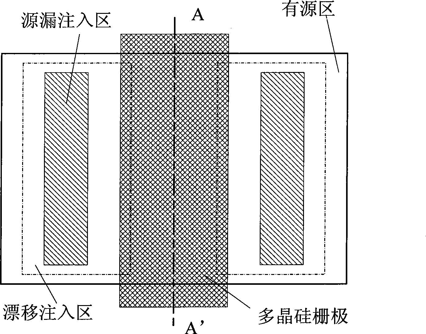
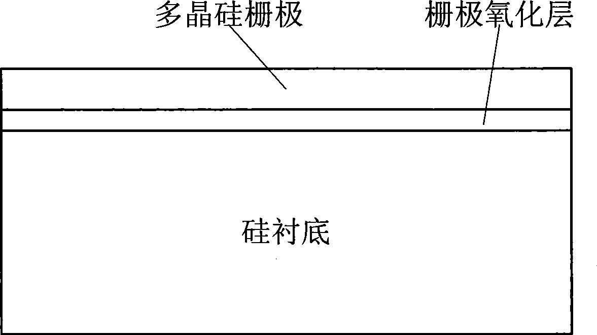

Image

  • Trench construction in MOS transistor
  • Trench construction in MOS transistor
  • Trench construction in MOS transistor

Examples


Embodiment Construction

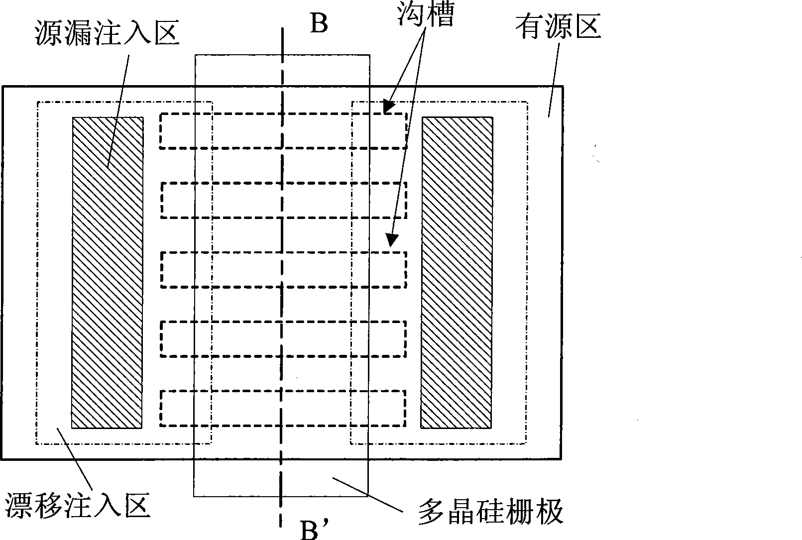
[0011] The channel structure in the MOS transistor of the present invention is provided with a plurality of trenches on the surface of the silicon substrate in the channel region, and the length direction of each trench is the same as that of the current generated in the channel region when the MOS transistor works. The direction of motion is the same.

[0012] image 3 It is a schematic diagram of the layout of a specific MOS transistor of the present invention. The channel region between the source and drain regions under the polysilicon gate region is provided with a plurality of grooves, and the length direction of the grooves is the same as that generated in the channel region when the transistor works. The direction of current movement is the same, which is the horizontal direction in the figure. Figure 4 for along image 3 Schematic cross-sectional view of the BB' plane. Because the working principle of the MOS transistor is to generate a current effect on the silic...


PUM


Abstract

The invention discloses a channel structure of an MOS transistor, which is used in the power MOS transistor. The surface of a silicon substrate in a channel zone is provided with a plurality of slots of which the lengthwise direction is the same as the moving direction of the current in the channel zone when the MOS transistor works. Because the channel zone is additionally provided with the slots, the channel is changed from a single plane to multi-planes, so that under conditions of not changing the size of the device, the effective length of the channel of the device is increased, and the driving capacity of the device is also enhanced.

Description

technical field [0001] The invention relates to a method for preparing a MOS transistor, in particular to a method for preparing a channel in a power MOS transistor. Background technique [0002] In VLSI, power MOSFETs are widely used in ultrasonic transducers, flat panel display drivers, communication circuits, integrated microsystems, automotive electronics, small DC motor control, inkjet printers, switching power supplies and in medical instruments. In these applications, the circuit is required to have a large output current. The channel in a conventional metal-oxide-semiconductor structure is planar, such as figure 1 with figure 2 As shown, the silicon surface between the source and drain implanted regions under the gate oxide layer of the polysilicon gate is the channel region. In order to increase the driving current of the device, it is often necessary to increase the width of the gate. But doing so will increase the area of ​​the device, which is not conducive...

Claims


Application Information

Patent Timeline
Patent Type & Authority Applications(China)
IPC IPC(8): H01L29/78H01L29/10
Inventor 陈华伦陈瑜熊涛罗啸陈雄斌
Owner SHANGHAI HUA HONG NEC ELECTRONICS
Learn More