
Electronic element

An electronic component and electrode technology, applied in the field of electronic components containing a transparent conductive layer, can solve the problems of insufficient mechanical and chemical durability, uneven distribution of resistance resistance, poor performance of electronic components, etc. The effect of improving performance, good toughness and mechanical strength

Active Publication Date: 2009-06-17
TSINGHUA UNIV +1
View PDF0 Cites 51 Cited by
  • Summary
  • Abstract
  • Description
  • Claims
  • Application Information

AI Technical Summary

Problems solved by technology

The above-mentioned ITO layer is currently mainly prepared by sputtering or vapor deposition. During the preparation process, a relatively high vacuum environment and heating to 200-300°C are required. Therefore, the preparation cost of the ITO layer is relatively high, so that correspondingly The cost of electronic components is higher
In addition, because the mechanical and chemical durability of the ITO layer is not good enough and the ITO layer is used as a transparent conductive layer, there are shortcomings such as uneven resistance distribution, which leads to poor performance of the existing electronic components.

Method used


Image

  • Electronic element
  • Electronic element
  • Electronic element

Examples


preparation example Construction

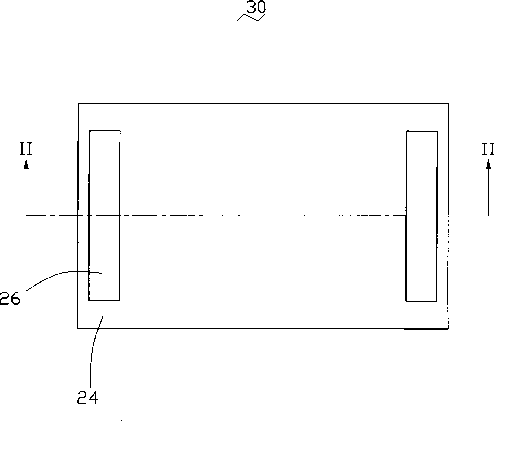
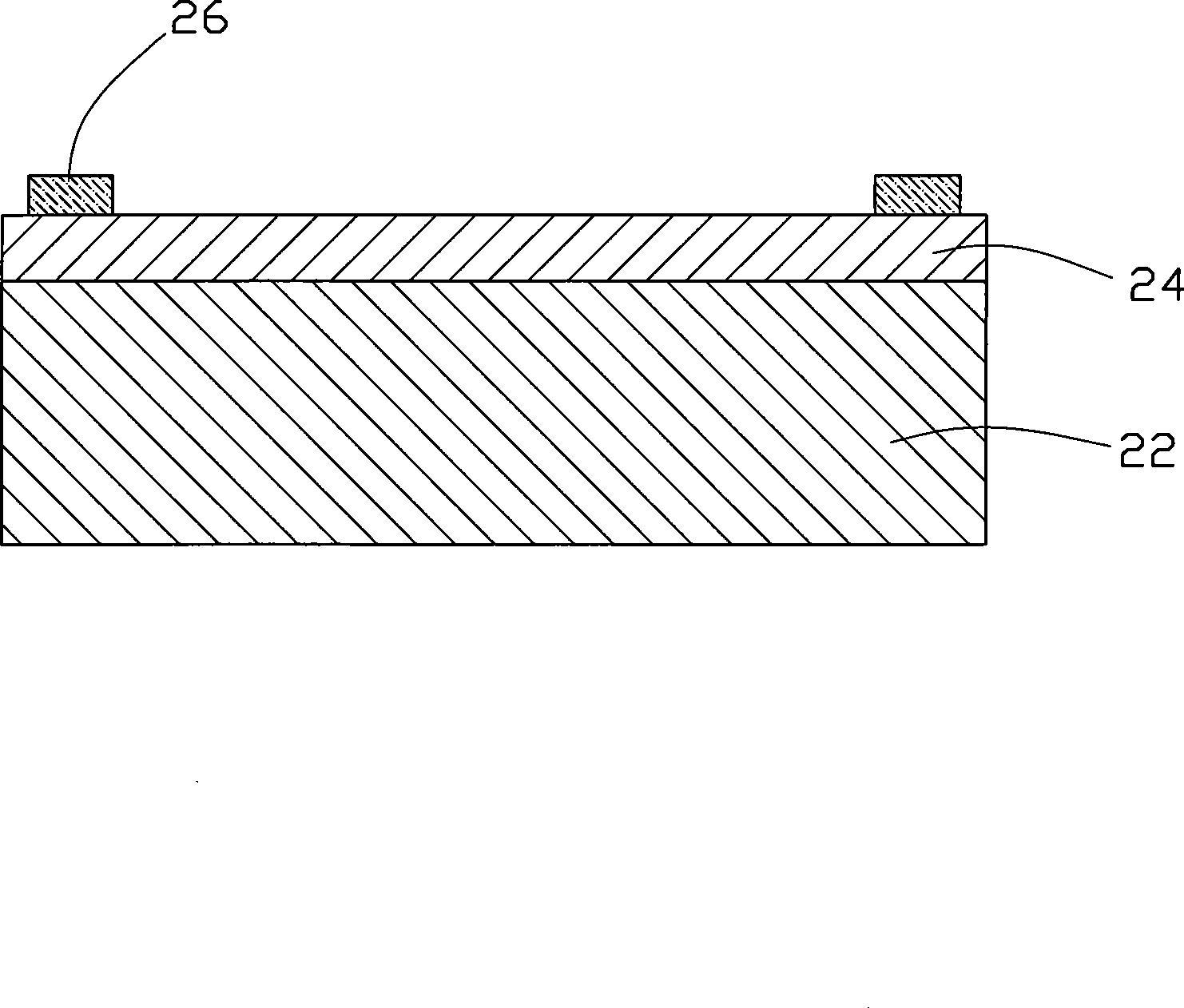
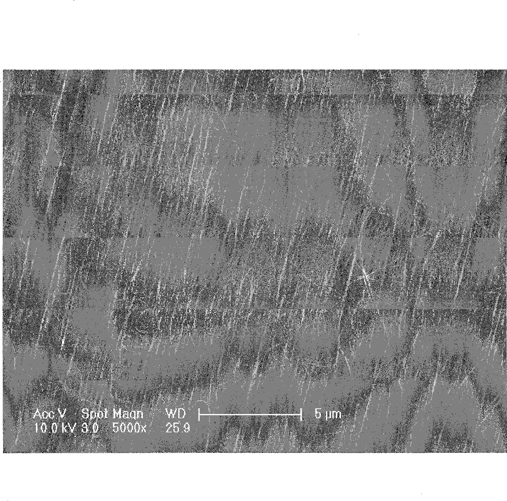
[0017] The transparent conductive layer 24 of the embodiment of the technical solution includes at least two overlapping carbon nanotube layers, each carbon nanotube layer includes a plurality of aligned carbon nanotubes, and the carbon in two adjacent carbon nanotube layers The nanotubes are aligned in different directions or aligned in the same direction. The preparation method of the above-mentioned transparent conductive layer 24 mainly includes the following steps:

[0018] Step 1: providing a carbon nanotube array, preferably, the array is a super-aligned carbon nanotube array.

[0019] The carbon nanotube array provided in the embodiment of the technical solution is a single-walled carbon nanotube array or a multi-walled carbon nanotube array. In this embodiment, the preparation method of the super-parallel carbon nanotube array adopts the chemical vapor deposition method, and its specific steps include: (a) providing a flat substrate, which can be a P-type or N-type s...


PUM

PropertyMeasurementUnit
widthaaaaaaaaaa
diameteraaaaaaaaaa
diameteraaaaaaaaaa

Abstract

The invention relate to an electronic element, comprising a substrate and a transparent conductive layer arranged on one surface of the substrate, wherein the transparent conductive layer comprises a carbon nanometer tube layer.

Description

technical field [0001] The invention relates to an electronic component, in particular to an electronic component containing a transparent conductive layer used in the fields of polarizers, electrode batteries, field emission displays and the like. Background technique [0002] Since Japanese scientist Iijima first discovered carbon nanotubes (CNT) in 1991 (Iilima S., Nature, vol 354, p56 (1991)), nanomaterials represented by carbon nanotubes have unique structures and properties aroused great concern. In recent years, with the continuous deepening of research on carbon nanotubes and nanomaterials, their broad application prospects continue to emerge. For example, due to the unique electromagnetic, optical, mechanical, and chemical properties of carbon nanotubes, a large number of researches on their application in fields such as field emission electron sources, sensors, new optical materials, and soft ferromagnetic materials have been continuously reported. [0003] The c...

Claims


Application Information

Patent Timeline
Patent Type & Authority Applications(China)
IPC IPC(8): H01B5/14C01B31/00G06F3/041
CPCH01L51/0048B82Y10/00B82Y30/00H01L31/022466H01L51/444H01L31/1884H01L51/102Y02E10/549Y10T428/24124Y10T428/263Y10T428/24628Y10T428/30Y10T428/26Y10T442/67Y10T428/249921Y10T442/60Y10T428/24942G06F3/0443H10K85/221H10K10/82H10K30/821B82B3/00B82Y25/00
Inventor 李群庆姜开利刘亮范守善
Owner TSINGHUA UNIV
Learn More