Eccentric crankshaft punching machine

A crankshaft punching and eccentric technology, applied in the field of mechanical processing equipment, can solve the problems of large volume, high noise, difficult large-area thin plate cutting, etc., and achieve the effect of small volume, low noise and reasonable structure

Inactive Publication Date: 2011-08-31
宁波澳玛特高精冲压机床股份有限公司
View PDF6 Cites 0 Cited by
  • Summary
  • Abstract
  • Description
  • Claims
  • Application Information

AI Technical Summary

Problems solved by technology

[0003] The present invention mainly solves the technical problems of large volume, high noise and difficulty in cutting large-area thin plates in the prior art, and provides an eccentric crankshaft punching machine

Method used


Image

  • Eccentric crankshaft punching machine
  • Eccentric crankshaft punching machine
  • Eccentric crankshaft punching machine

Examples


Embodiment

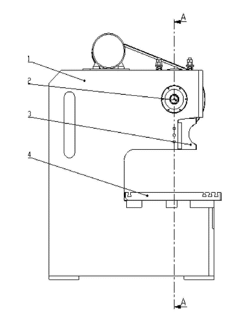
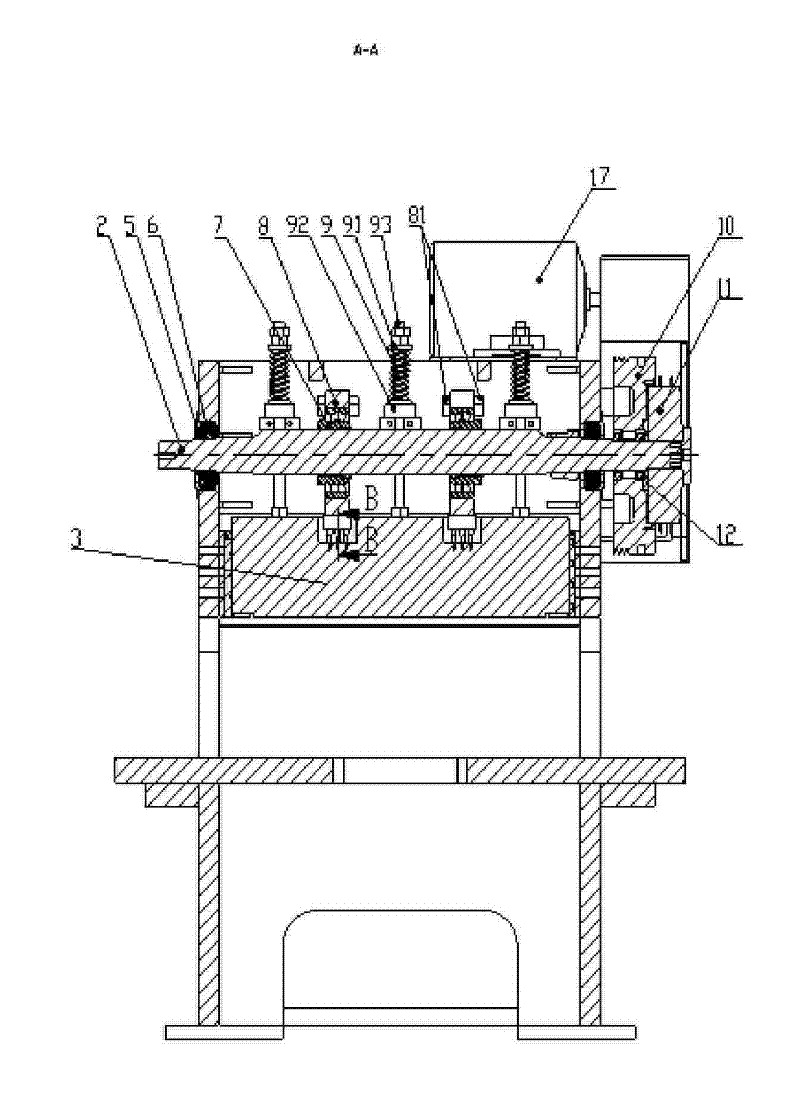
[0022] Embodiment: a kind of eccentric crankshaft press of the present invention, as attached figure 1 , attached figure 2 , attached image 3 , attached Figure 4 , shown in accompanying drawing 5, it comprises frame 1, workbench 4, drive motor 17 and the crankshaft 2 that is connected with it by transmission mechanism, be located at crankshaft 2 below and the slide block 3 of bottom installation mould.

[0023] The crankshaft 2 is an eccentric shaft, and its eccentric part is covered with a rolling body 7, and the outer peripheral surface of the rolling body 7 forms a rigid contact with the slider 3 directly or through a transition piece, which can transmit a downward force. The rolling elements 7 are set as two sets on the crankshaft 2 . The crankshaft 2 is made in one piece, and its eccentric part is formed by a cylinder deviated from the axis line on the shaft body. The rolling element 7 is a roller self-aligning bearing, and its inner ring is fixed on the crankshaf...


PUM


Abstract

The invention relates to an eccentric crankshaft punch. A crankshaft is an eccentric shaft, an eccentric part is sleeved with a rolling element, and a sliding block arranged below the crankshaft and provided with a die at the bottom is provided with a spring which forms an upward acting force to the sliding block; and the sliding block forms vertically moving punching motion under the combined actions of the upward acting force formed by compressing the spring and a downward acting force formed by rotation of the crankshaft. By adopting the structure, the crankshaft is easy to process with low cost; a punching stroke is short and suitable for cutting thick plates; the punching force is smaller so as to cause low noise during punching; and particularly the die with larger working area can be mounted in the structure, so that the structure is suitable for cutting of the plates with large area.

Description

technical field [0001] The invention relates to a mechanical processing equipment, in particular to an eccentric crankshaft punching machine. Background technique [0002] For thin plates with a relatively large area, the equipment used for cutting requires less punching force, short punching stroke, and large force-bearing area. For traditional stamping equipment, the stamping force is large, but the bed is huge, which produces a lot of noise during stamping, which limits the production of products. In addition, it is difficult to provide a corresponding working area for plates with a large area. Lack of flexible adaptation to molds with large working areas, it is difficult to meet the specific processing requirements of thin plates of different specifications in actual production. Therefore, how to solve the problems encountered above has become a necessity. Contents of the invention [0003] The invention mainly solves the technical problems of large volume, high nois...

Claims


Application Information

Patent Timeline
Patent Type & Authority Patents(China)
IPC IPC(8): B21D28/00B21D28/20
Inventor 竺银军
Owner 宁波澳玛特高精冲压机床股份有限公司
Why Eureka
Try Eureka