Automatic adjustable dragging method pipe

A technology of adjustable and drawn tubes, applied in the direction of engine components, lifting valves, valve details, etc., can solve the problems affecting the working efficiency and batching accuracy of the pneumatic conveying system, and the large fluctuation of working pressure, so as to save compressed air and materials The effect of improving the flow capacity and reducing the influence of airflow stability

Inactive Publication Date: 2009-06-24
MESNAC
View PDF0 Cites 7 Cited by
  • Summary
  • Abstract
  • Description
  • Claims
  • Application Information

AI Technical Summary

Problems solved by technology

Due to the simulation and rough adjustment of the diameter of the Lafah tube, the problem of large fluctuations in working pressure is prone to occur, which affects the working efficiency and batching accuracy of the pneumatic conveying system

Method used


Image

  • Automatic adjustable dragging method pipe
  • Automatic adjustable dragging method pipe
  • Automatic adjustable dragging method pipe

Examples


Embodiment 1

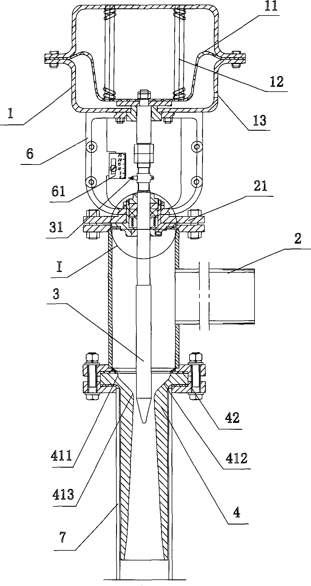
[0035] Example 1, such as Figure 1 to Figure 3 As shown, the automatic adjustable puller tube includes an automatic pressure regulator 1 , an air inlet pipe 2 , an adjustment rod 3 , a fixed puller tube 4 , a sealing disc 5 , a dial 6 and an air tube 7 . in,

[0036] An air pipe 7 is sheathed outside the fixed puller pipe 4 .

[0037] The intake pipe 2 and the fixed Laf pipe 4 are fixedly connected to each other through flanges and bolts 42 .

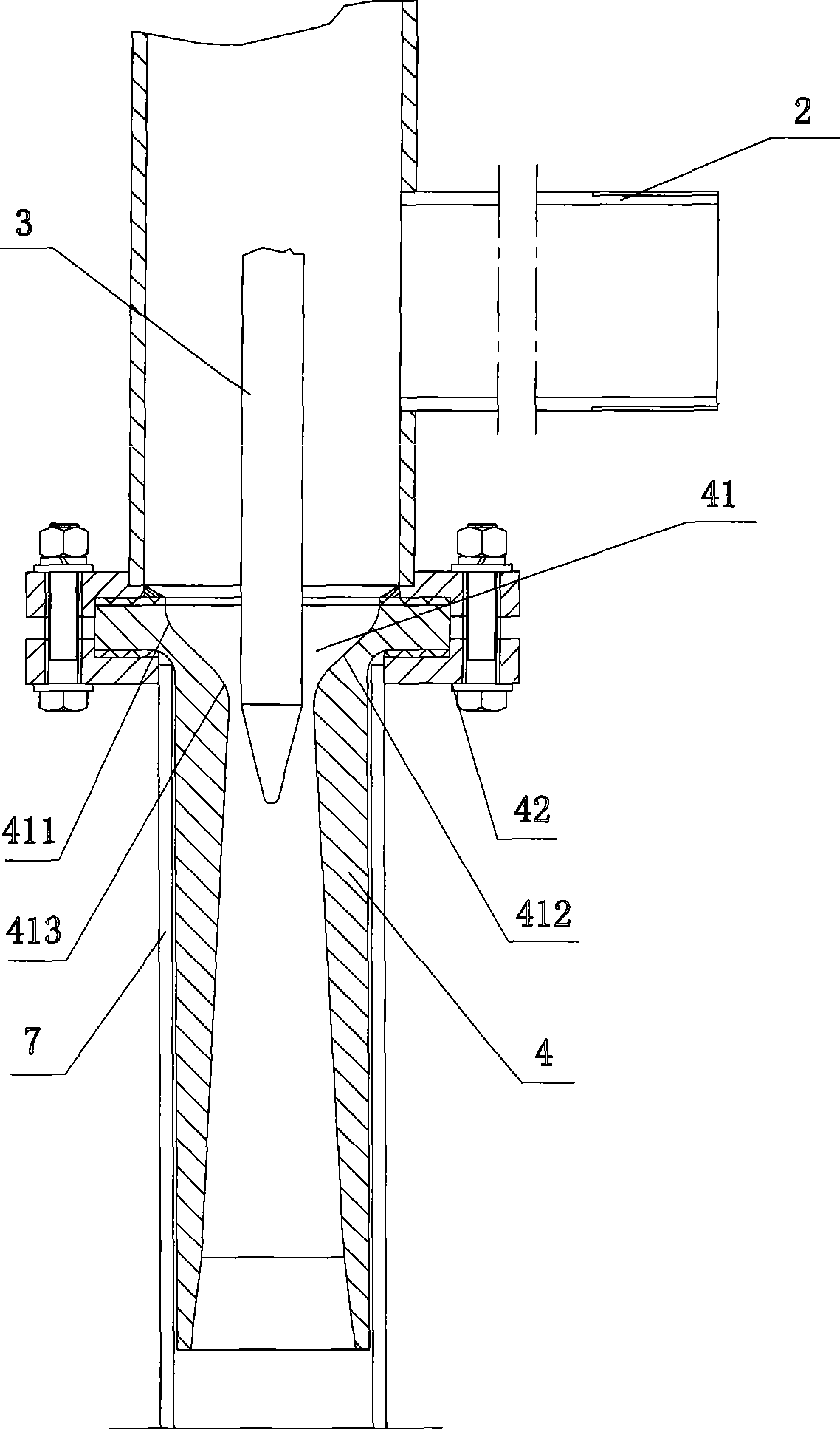
[0038] The adjusting rod 3 runs through the air intake pipe 2, its outer end is connected to the automatic pressure regulator 1, and its inner end extends into the entrance 41 of the fixed puller pipe 4, and the end of the adjusting rod 3 is set to be tapered .

[0039] The section at the entrance 41 has a funnel-shaped curve structure, the curve 411 is a section of arc whose center is on the inlet interface of the fixed drawing pipe 4, and the curve 413 is the minimum cross section of the throat of the fixed drawing pipe 4 Curve 4...


PUM


Abstract

The invention relates to an automatic adjustable laval pipe, which can automatically change the pipe diameter of the laval pipe, realize adjustment of the required air quantity according to the characteristics of materials, provide stable air flow under the condition of air pressure fluctuation, and is suitable for a material conveying system which requires regular adjustment of the air quantity. The automatic adjustable laval pipe mainly comprises an air inlet pipe, a regulating stem and a fixed laval pipe, wherein the air inlet pipe and the fixed laval pipe are fixedly connected with each other; the regulating stem runs through the air inlet pipe; the outer end part of the regulating stem is connected with an automatic pressure regulator, and the inner end part of the regulating stem is extended into an inlet of the fixed laval pipe; a cross section of the inlet is provided with a funnel-shaped curved structure; a first section of curve is a section of circular arc of which the circle center is on an inlet interface of the fixed laval pipe; a third section of curve is a section of circular arc of which the circle center is on a minimum cross section on a throat section of the fixed laval pipe; and a second section of curve is a common tangent line which connects the first section of curve and the third section of curve.

Description

technical field [0001] The invention relates to an automatic adjustable puller tube for pneumatically conveying powder and granular materials, which belongs to the field of mechanical manufacturing. Background technique [0002] At present, fluidized pneumatic conveying is generally used for conveying powdery and granular materials. Adjusting the flow and velocity of compressed gas is the key technical factor to realize pneumatic conveying of materials. [0003] When transporting materials in closed pipelines, Laffer tubes are usually used to provide a stable air flow in the pipeline. The existing Lafah pipes are generally fixed, and the diameter of the Lafah pipe is initialized according to the material conveying characteristics before being installed in a specific pipeline or transporting a specific material. The disadvantage of using the current fixed Lafayette tube is that the tube diameter cannot be adjusted, so it can only be applied to the transportation of several t...

Claims


Application Information

Patent Timeline
Patent Type & Authority Applications(China)
IPC IPC(8): B65G53/66F16K1/00F16K31/12
Inventor 李勇郭永吉蒋存刚高天宝王兵
Owner MESNAC
Why Eureka
Try Eureka