Thermal conductivity coefficient measurement instrument for solid material
A technology of thermal conductivity and solid materials, which is applied in the field of material thermal conductivity testing, can solve the problems of low accuracy and achieve the effect of reducing production costs and high stability
- Summary
- Abstract
- Description
- Claims
- Application Information
AI Technical Summary
Problems solved by technology
Method used
Image
Examples
Embodiment 1
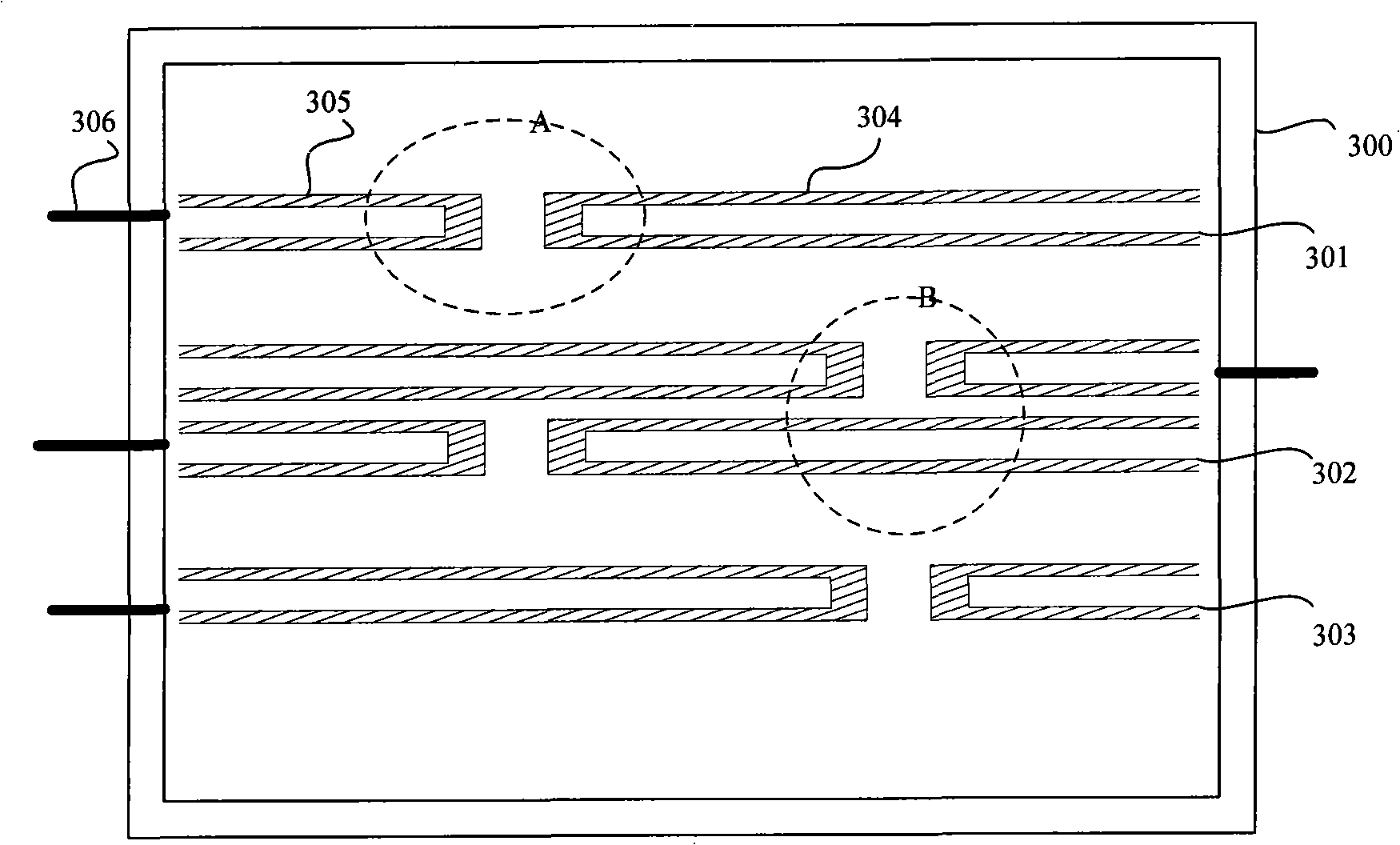
[0059] refer to image 3 A top view of the structure of the heating chip of the present invention shown, and Figure 4 and Figure 5 gives image 3 The schematic diagram of the enlarged structure of local area A and local area B in the middle shows the size of the heating wire used in the present invention, the unit is mm in the figure, and the material selected for the heating sheet is a 20 μm thick pure nickel sheet.
[0060] From image 3 It can be seen from the figure that a solid material thermal conductivity measuring instrument of the present invention includes: a heating sheet 300 for generating heat, and the heating sheet 300 includes: a first heating belt 301, a second heating belt 302, and a third heating belt distributed side by side. 303; the first heat band 301 and the third heat band 303 respectively include a first rectangular groove 304 and a second rectangular groove 305, the second heat band 302 includes two first rectangular grooves 304 and two second re...
Embodiment 2
[0067] The measurement principle of the constant voltage source measuring instrument and the corresponding measuring instrument device are described in detail below in conjunction with the accompanying drawings:
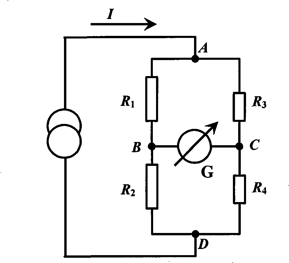
[0068] refer to Figure 6 The schematic diagram of the equivalent circuit of the heating chip of the present invention is shown, in this embodiment, a constant voltage is applied to the heating chip, that is, in Figure 6 A constant voltage is applied between points A and D of the Wheatstone bridge shown, as Figure 7 As shown in the schematic diagram of the device structure, the measuring instrument includes a constant voltage source 005 for providing energy to the heating plate 003, a material to be tested 004 and a material to be tested 002 respectively attached to the upper and lower surfaces of the heating plate 003 (in this embodiment, the material to be tested is The test material 004 and the test material 002 are the same), the data acquisition system 006 fo...
Embodiment 3
[0110] The measurement principle of the constant power source measuring instrument and the corresponding measuring instrument device are described in detail below in conjunction with the accompanying drawings:
[0111] In this embodiment, a constant power source with stable output power is used to provide energy to the heating plate, so as to obtain another experimental measurement device and corresponding measurement principle for measuring thermal conductivity. The structure of the heating plate is as image 3 As shown, the structure diagram of the constant power measuring instrument is shown in Figure 11 As shown, the biggest difference between the constant power source and the constant voltage source is that the internal circuit is different, refer to Figure 6 shown in the equivalent circuit diagram; and, combined with Figure 12 Analyze the equivalent circuit diagram of the constant power source;
[0112] When the material to be tested is measured with a constant pow...
PUM
| Property | Measurement | Unit |
|---|---|---|
| length | aaaaa | aaaaa |
| width | aaaaa | aaaaa |
| thermal conductivity | aaaaa | aaaaa |
Abstract
Description
Claims
Application Information
 - R&D
- Intellectual Property
- Life Sciences
- Materials
- Tech Scout
- Unparalleled Data Quality
- Higher Quality Content
- 60% Fewer Hallucinations
Browse by: Latest US Patents, China's latest patents, Technical Efficacy Thesaurus, Application Domain, Technology Topic, Popular Technical Reports.
© 2025 PatSnap. All rights reserved.Legal|Privacy policy|Modern Slavery Act Transparency Statement|Sitemap|About US| Contact US: help@patsnap.com


