

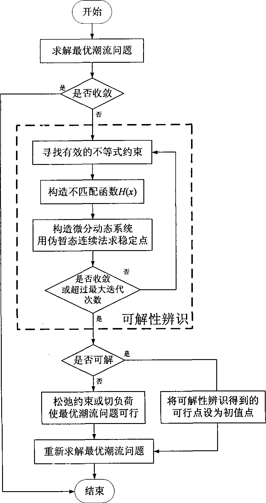
Optimum tide solvability identification method for electric power system
An optimal power flow and power system technology, applied in system integration technology, information technology support system, electrical components, etc., can solve problems such as insufficient algorithm robustness, excessive system load, unsolvable problems, etc., to improve economic and safety effect
- Summary
- Abstract
- Description
- Claims
- Application Information
AI Technical Summary
Problems solved by technology
Method used
Image

Examples
Embodiment 1
[0067] Consider the power system optimal power flow problem in the form of (1), where the optimization variable is x, which includes [P G , Q G , V e , V f ,], where P G and Q G are the active output and reactive output of the generator respectively, V e and V f are the real and imaginary parts of the voltage at each node, respectively.
[0068] The objective function is set as the minimum fuel cost of system power generation (9), where α is the economic coefficient of each generator.
[0069] f ( x ) = Σ ( α i 2 P Gi 2 + α i 1 P Gi + α i 0 ...
Embodiment 2
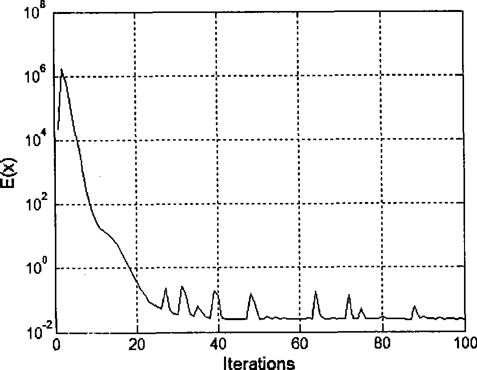
[0084] This embodiment uses the same optimal power flow model and precondition matrix as in Embodiment 1. Consider a power system with 678 nodes (including 170 generators and 919 lines). When the interior point method is used to solve the optimal power flow problem, it cannot converge, and setting the initial value point as a flat start or a power flow solution cannot make it converge.
[0085] Applying the power system optimal power flow solvability identification proposed by the present invention to this system, after 100 iterations (taking 4.10 seconds), the energy function value is 2.5E-2, which does not meet the convergence condition. During the calculation process, the energy function change curve is shown in figure 2 , it can be seen from the figure that the energy function can never converge. Therefore, it can be considered that the optimal power flow problem of this example has no solution itself, and it cannot be converged by using other optimization algorithms or...
Embodiment 3
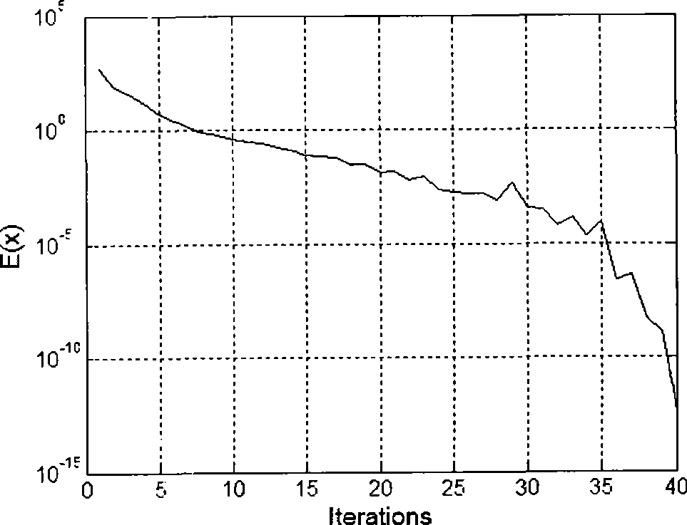
[0087] This embodiment uses the same optimal power flow model and precondition matrix as in Embodiment 1. Consider a power system with 2052 nodes (including 211 generators and 2533 lines). When the interior point method is used to solve the optimal power flow problem, it cannot converge, and setting the initial value point as a flat start or a power flow solution cannot make it converge.
[0088] Applying the power system optimal power flow solvability identification test proposed by the present invention to this system, it converges after 39 iterations (taking 4.97 seconds), and the energy function value after convergence is 4.2E-13. During the calculation process, the change curve of the energy function is shown in image 3 , it can be seen from the figure that the energy function quickly drops to near 0. Therefore, it can be considered that the optimal power flow problem of this example is feasible, and the optimal solution will be obtained when an appropriate optimizatio...
PUM
 Abstract
Description
Claims
Application Information