Radiator

A heat sink and heat dissipation fin technology, which is applied in the direction of electrical solid devices, semiconductor devices, cooling/ventilation/heating transformation, etc., can solve the problems of complex structure, inconvenient assembly, easy existence of air gaps, etc., and achieve high heat transfer speed, Large thermal contact area and improved heat dissipation effect

Inactive Publication Date: 2009-06-24
HONG FU JIN PRECISION IND (SHENZHEN) CO LTD +1
View PDF0 Cites 8 Cited by
  • Summary
  • Abstract
  • Description
  • Claims
  • Application Information

AI Technical Summary

Problems solved by technology

This heat sink includes a base and a plurality of mutually parallel heat dissipation fins extending from the base. When using this heat sink to dissipate heat for those in-line electronic components, a plurality of heat sinks are fixed by a fastener. Make thermal contact between the electronic components and the electronic components. However, after the heat sink is fixed, there is an air gap between the electronic components and the heat dissipation effect is not good. The structure of the fixing mode is complicated and the assembly is inconvenient.

Method used


Image

  • Radiator
  • Radiator
  • Radiator

Examples


Embodiment Construction

[0013] Further description will be made below in conjunction with the embodiments with reference to the accompanying drawings.

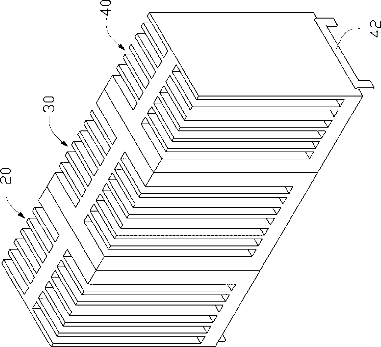
[0014] Such as figure 1 As shown, it is the first embodiment of the present invention. The radiator includes a first heat dissipation fin group 20, a second heat dissipation fin group 40 and a A third cooling fin group 30 between them.

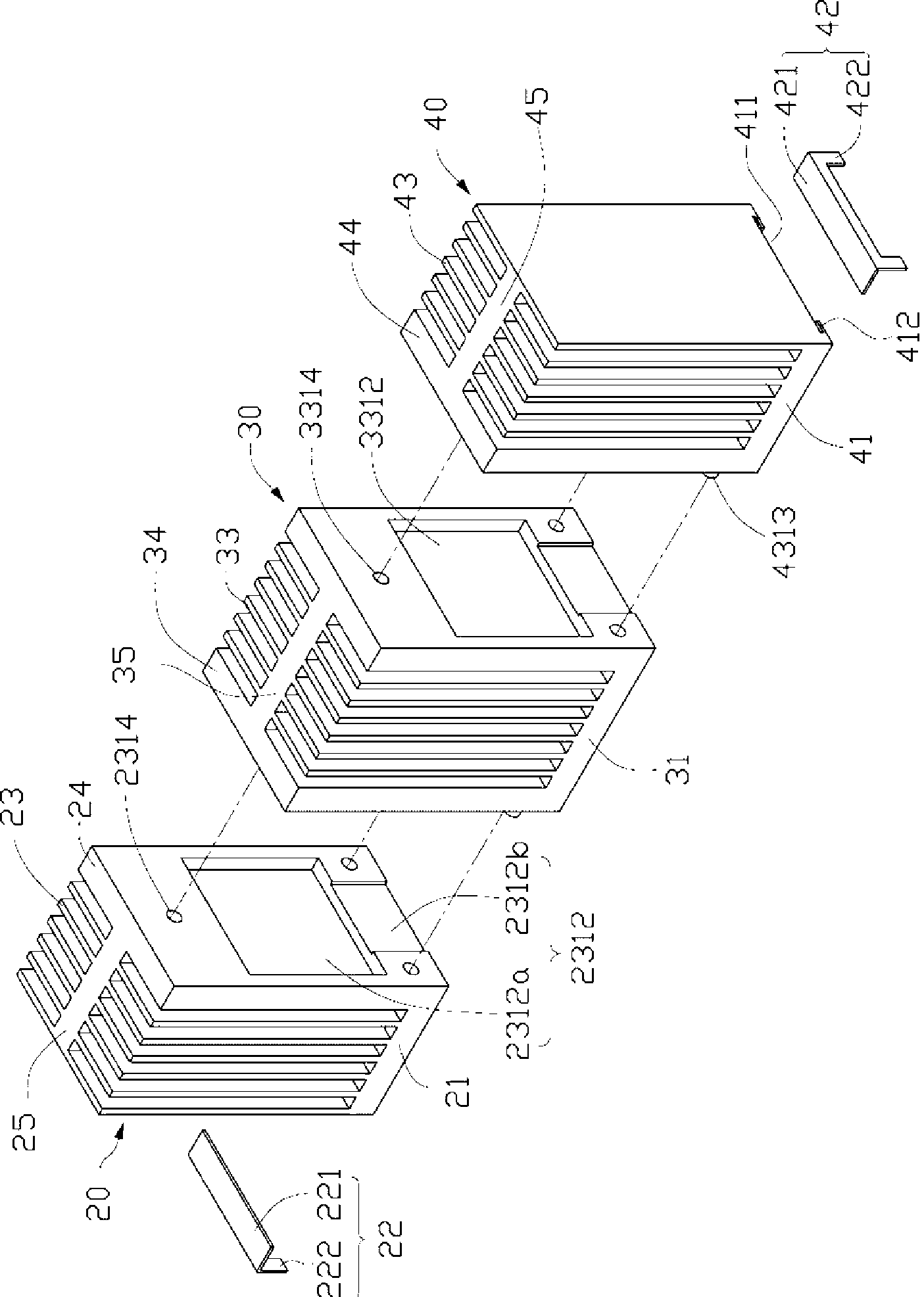
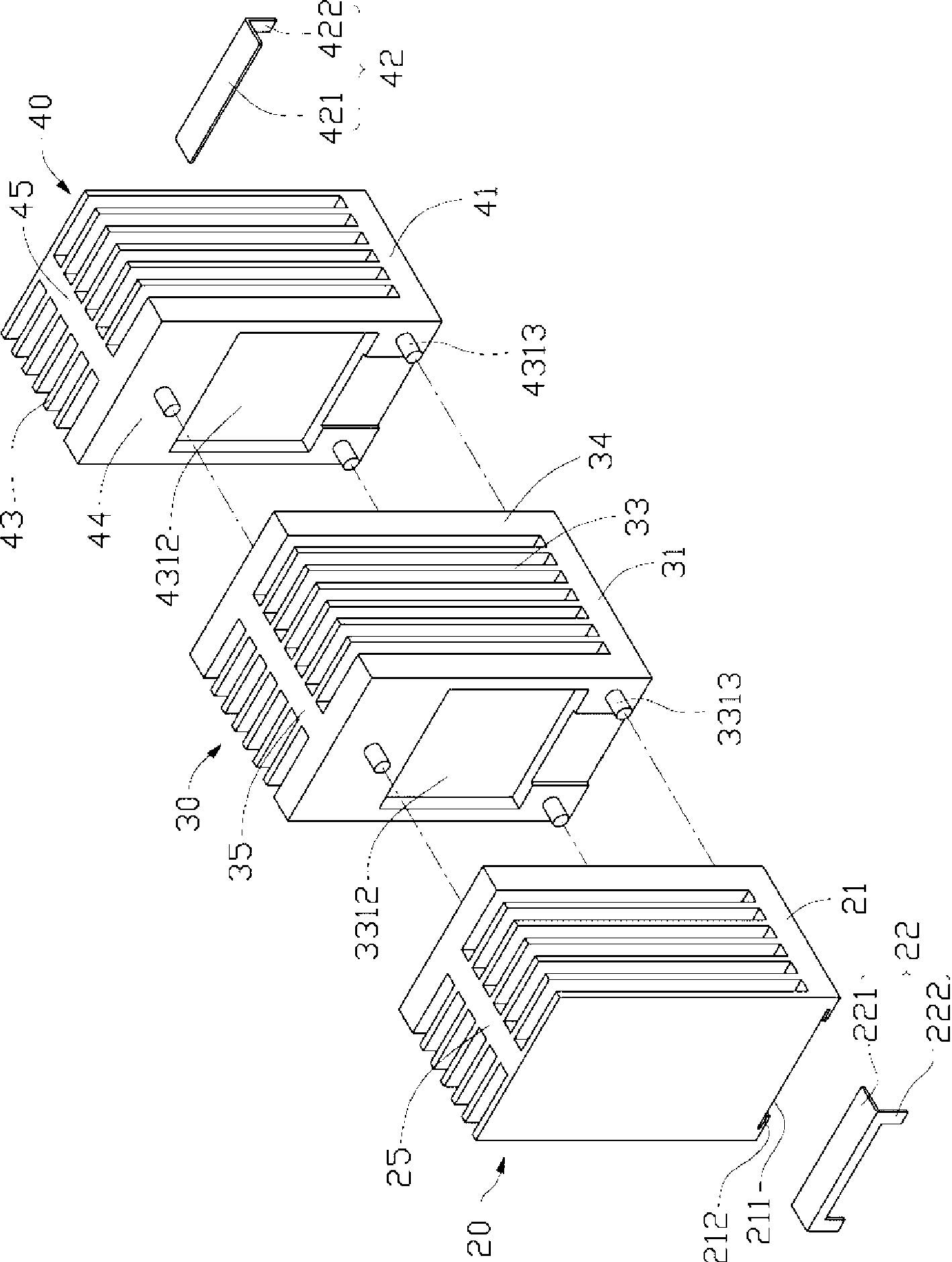
[0015] Please also refer to figure 2 and image 3 The first heat dissipation fin group 20 includes a flat base 21, a fixing frame 22 arranged under the base 21, a plurality of heat dissipation fins 23 extending upward from the base 21, and a plurality of heat dissipation fins 23 extending upward from the edge of the base 21. The side plate 24 and a heat dissipation wall 25 connected between the plurality of heat dissipation fins 23 . The base 21 has opposite upper and lower surfaces, and the plurality of cooling fins 23 vertically extend upward from the upper surface of the base 21 and are arranged parallel to e...


PUM


Abstract

The invention relates to a heat radiator, comprising a first radiating fin group and a second radiating fin group, wherein, each radiating fin group comprises a side plate arranged at one side of the radiating fin group and a plurality of radiating fins connected with the side plate; the side plate of the first radiating fin group is jointed with the side plate of the second radiating fin group; at least one side plate is sagged downwards to form a containing part used for containing a direct-insertion heating electronic component; and the electronic component is contained in the containing space between the two radiating fins. The contact area between the electronic component and the radiator is large, and the heat transfer rate is high, so as to improve the heat radiating effect.

Description

technical field [0001] The invention relates to a radiator, in particular to a radiator suitable for dissipating heat from in-line electronic components. Background technique [0002] With the continuous advancement and wide application of large-scale integrated circuit technology, computers are widely used in all walks of life. In order to adapt to the development trend of increasing data processing volume and increasing timeliness requirements, the functions of various electronic components are becoming more and more powerful. , so that a large amount of heat is generated per unit time. If the heat is not removed in time, the temperature of the electronic components will rise, which will have a great impact on the safety and performance of the system. [0003] Usually, the industry installs a heat sink on one side of the electronic component to assist its heat dissipation. At the same time, a fan is installed on the heat sink to provide forced air flow to promote the heat ...

Claims


Application Information

Patent Timeline
Patent Type & Authority Applications(China)
IPC IPC(8): H05K7/20H01L23/36
Inventor 马红钢黄旭韦维韦振敏
Owner HONG FU JIN PRECISION IND (SHENZHEN) CO LTD
Why Eureka
Try Eureka