Illuminator structure for vehicle

A technology for illuminators and vehicles, which is applied to road vehicles, lighting devices, fixed lighting devices, etc., can solve the problems of easy light diffusion of bulbs, and achieve the effects of uniform light distribution, improved additional functions, and improved appearance.

Active Publication Date: 2011-04-20
HONDA MOTOR CO LTD
View PDF1 Cites 0 Cited by
  • Summary
  • Abstract
  • Description
  • Claims
  • Application Information

AI Technical Summary

Problems solved by technology

[0004] However, in the above-mentioned prior art, light distribution is performed only on the bulb light leaking from the gap around the main reflector and the opening provided in the main reflector, so the bulb light is easy to diffuse, and it becomes a problem to ensure sufficient brightness.

Method used


Image

  • Illuminator structure for vehicle
  • Illuminator structure for vehicle
  • Illuminator structure for vehicle

Examples


Embodiment Construction

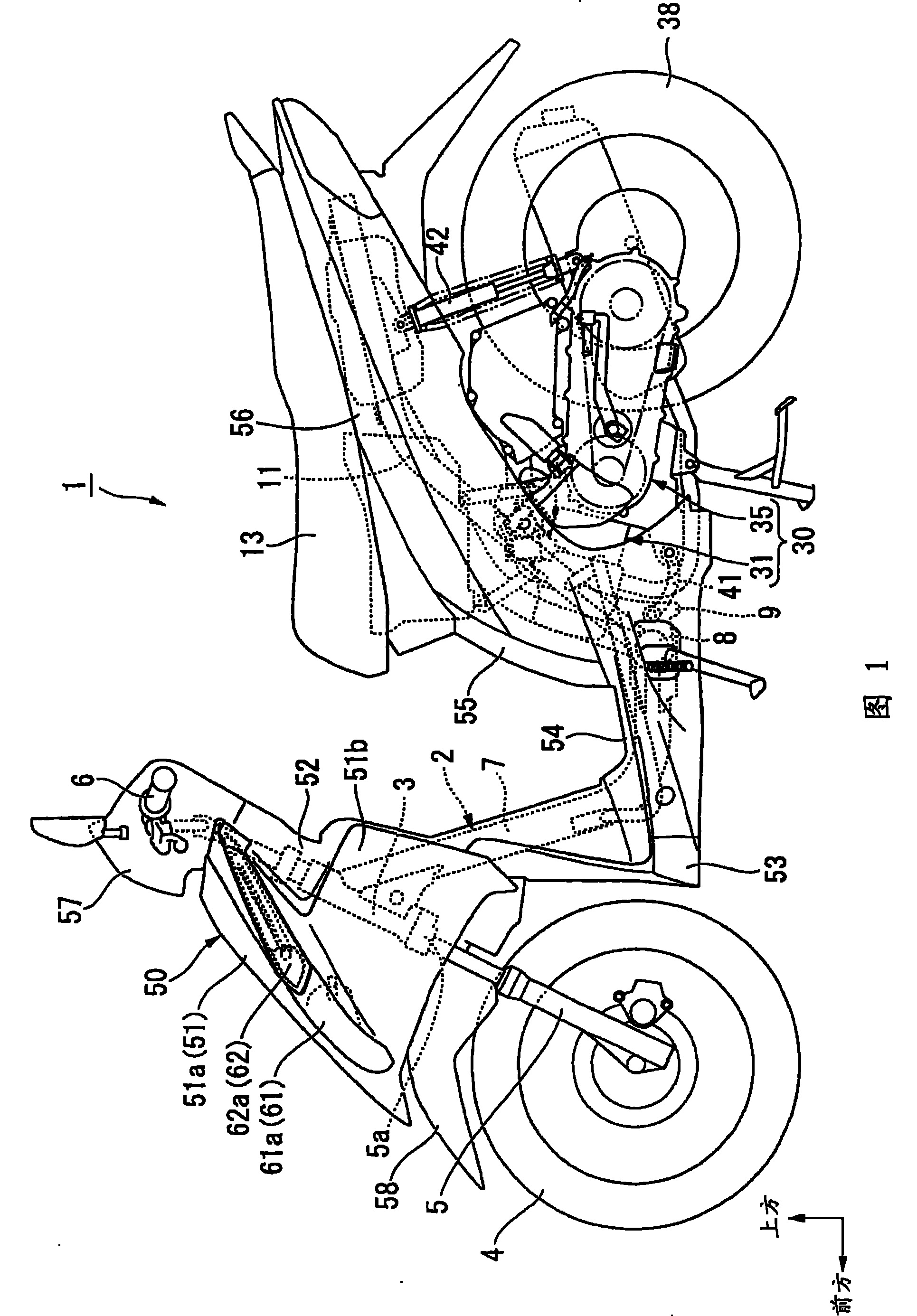
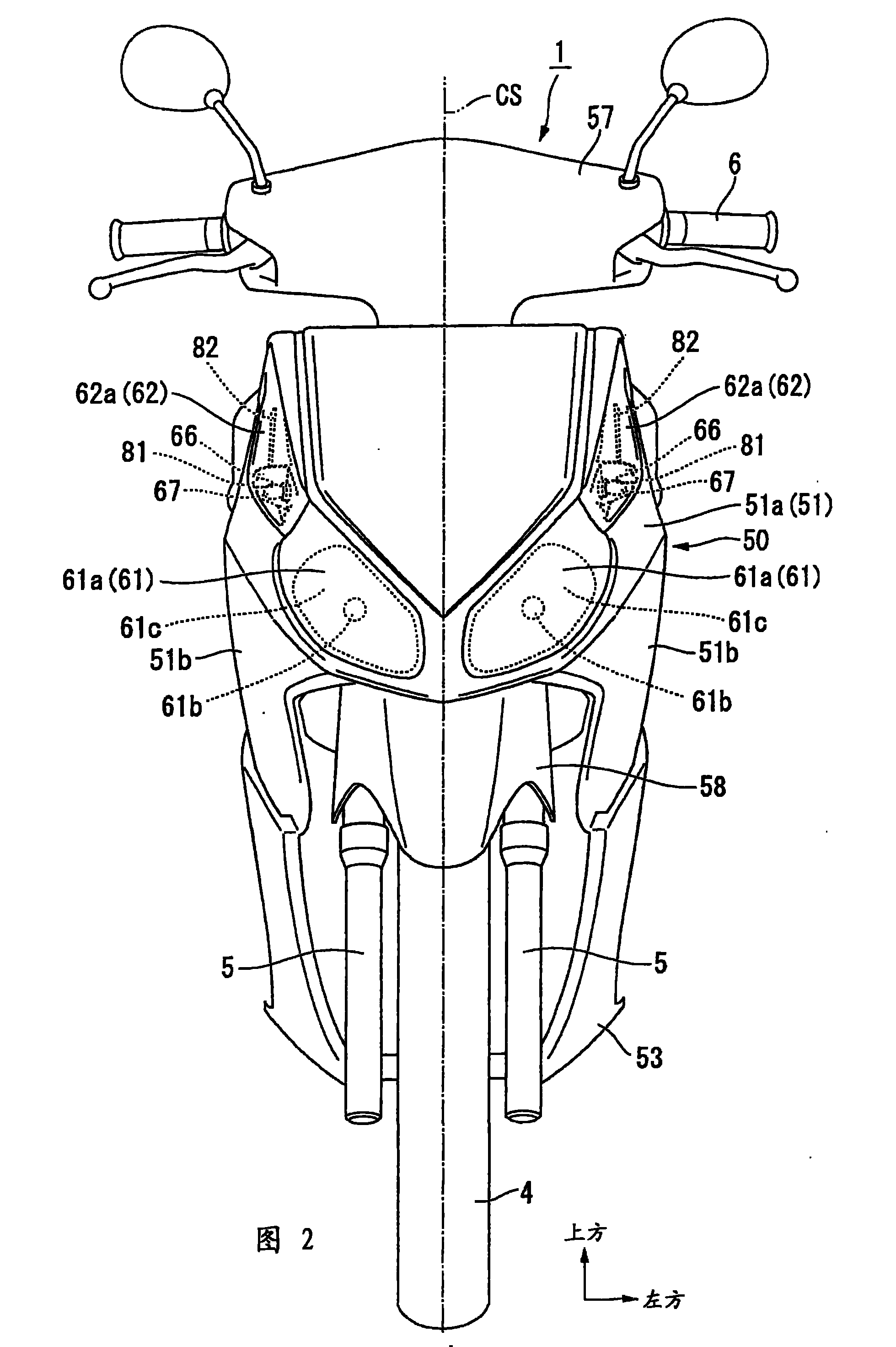
[0033] Embodiments of the present invention will be described below with reference to the drawings. Directions such as front, rear, left, and right in the following description are the same as the directions of the vehicle unless otherwise specified. Arrow FR in the figure indicates the front of the vehicle, arrow LH indicates the left side of the vehicle, and arrow UP indicates the upper side of the vehicle.

[0034] In the motorized two-wheeled vehicle (saddle type vehicle) 1 of the scooter type shown in FIGS. 2 3 places on the head pipe at the front end. A handlebar 6 for steering is attached to the upper portion of the steering shaft 5a. A line CS in FIG. 2 indicates the left and right center planes of the vehicle body.

[0035] The body frame 2 has a main frame 7 extending obliquely downward and rearward from the head pipe 3, and is of a low-frame type to improve the ease of straddling by making the lower part between the head pipe 3 and the seat 13 for a rider. The l...


PUM


Abstract

A structure of vehicular illuminator can ensure enough brightness of bulb light transmitting to different directions and can execute reliable light distribution in the structure of vehicular illuminator which executes light distribution in the direction different from the reflection direction of main reflector. The structure of vehicular illuminator is provided with the following components: a notch (81) which is formed on a main reflector (67) and guides the bulb light to the back side of main reflector (67), and an auxiliary reflector (82) which extends to the back part of main reflector (67) along the irradiation direction of bulb light guided by the notch (81). The bulb light which passes through the notch (81) and is guided to the back part of main reflector (67) is executed with light distribution in a direction different from the reflection direction of main reflector (67) by the auxiliary reflector (82).

Description

technical field [0001] The present invention relates to a vehicle illuminator structure suitable for motorcycles and the like. Background technique [0002] Conventionally, some vehicle illuminator structures for motorcycles are capable of distributing light from a bulb in a direction different from the reflection direction of a main reflector (for example, refer to Patent Document 1). [0003] Patent Document 1: (Japanese) Unexamined Patent Publication No. 2007-83894 [0004] However, since the above-mentioned prior art distributes light only to the bulb light leaking from the gap around the main reflector and the opening provided in the main reflector, the bulb light is easily diffused, and it is a problem to ensure sufficient brightness. Contents of the invention [0005] It is an object of the present invention to ensure sufficient brightness of the bulb light in the different directions and to ensure sufficient luminance and For reliable light distribution. [0006...

Claims


Application Information

Patent Timeline
Patent Type & Authority Patents(China)
IPC IPC(8): F21W101/027F21V7/10B62J6/00F21S8/10F21V7/04F21W107/17F21Y101/00
Inventor 段原崇中岛广幸滝本幸子久保田吉隆
Owner HONDA MOTOR CO LTD
Why Eureka
Try Eureka