Light conducting plate carved by laser impulse and method for producing the same

A technology of laser pulse and light guide plate, applied in light guide, engraving, light guide of lighting system, etc., can solve the problems of large chemical ink, low brightness, poor light refraction effect, etc., and achieve exquisite technical specifications, high light conversion rate, and luminescence high efficiency effect

Inactive Publication Date: 2009-07-01
SHANGHAI EDGE LIGHT IND
View PDF0 Cites 24 Cited by
  • Summary
  • Abstract
  • Description
  • Claims
  • Application Information

AI Technical Summary

Problems solved by technology

[0006] Disadvantages: different sizes require different stencils, the stencil must be successful once, otherwise it will be scrapped, and the refraction effect on light is worse than that of non-printing, that is, the brightness is low; chemical ink is greatly affected by the environment, easy to age and turn yellow ; All manual operation, poor stability and uniformity
[0010] Disadvantages: the mold cost is large, different sizes of products need different molds, the cost of plastic molds is high, the size parameters of the dots cannot be modified after the mold is finalized, the mold must be successfully opened once, otherwise it will be scrapped, and the production process is difficult to master. Produce large light guide plates, this method is mainly for small liquid crystal display backlight products
[0014] Disadvantages: equipment research and development investment costs are relatively large

Method used


Image

  • Light conducting plate carved by laser impulse and method for producing the same
  • Light conducting plate carved by laser impulse and method for producing the same
  • Light conducting plate carved by laser impulse and method for producing the same

Examples


Embodiment Construction

[0035] The present invention is specifically described below in conjunction with accompanying drawing

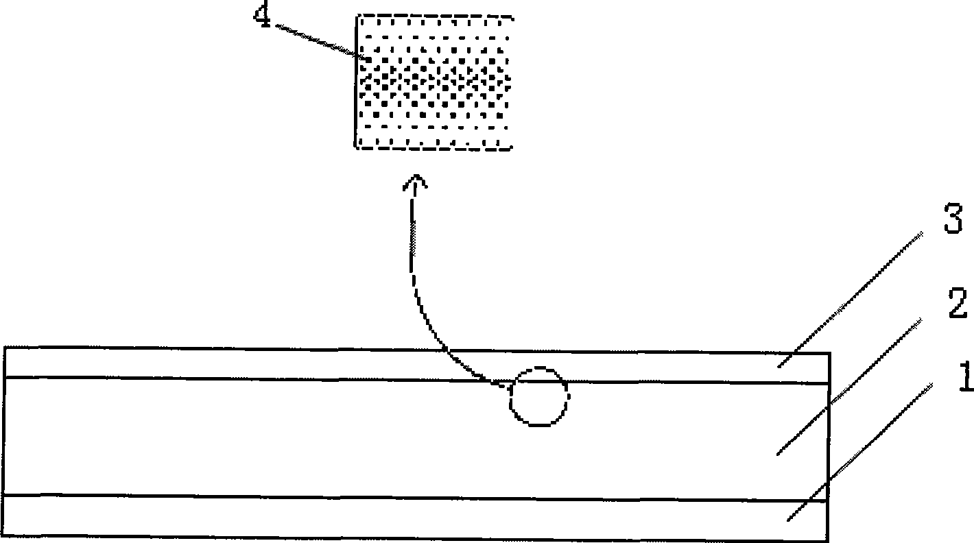
[0036] see figure 1 , a kind of light guide plate utilizing laser pulse engraving according to the present invention, the light guide plate made of acrylic flat plate includes a reflective layer 1 made of a high reflectivity material, a high light transmittance material The light guide layer 2 made and the diffusion layer 3 made of homogeneous material are composed; it is characterized in that the light guide layer 2 of the light guide plate is distributed with reflective diffusion points or diffusion grooves 4 engraved with laser pulses; the diffusion The distance between the dots or diffusion grooves is less than or equal to 5mm, the depth is 0.001-1mm controlled by laser energy, and the diameter of the diffusion dots is 0.005-2mm.

[0037] In addition, the reflective layer of the light guide plate is a layer of PET (polyethylene terephthalate) material with high light re...


PUM


Abstract

The invention discloses a light guide plate engraved by laser pulse, which comprises a reflective layer made of high reflective non-light-absorptive materials, a light guide layer made of high light transmittance materials and a diffusion layer made of light uniform scattering materials. The light guide plate is characterized in that reflecting diffusion sites or diffusion grooves engraved by laser pulse are distributed on the light guide layer of the light guide plate, spacing among the reflecting diffusion sites or diffusion grooves is smaller than or equal to 5mm, the depth of the reflecting diffusion sites or diffusion grooves under control of laser energy ranges from 0.001mm to 1mm, and the diameter of the diffusion sites ranges from 0.005mm to 2mm. In addition, the invention further discloses a method for preparing the light guide plate. The light guide plate manufactured by the method has the advantages of ultra-thinness, super-brightness, uniform light scattering, saving energy, environmental protection, durability, etiolation resistance, fast and simple installation and maintenance and the like without dark spaces.

Description

Technical field: [0001] The invention relates to a light guide material used in lighting equipment, in particular to a light guide plate engraved by laser pulses and a preparation method thereof. Background technique: [0002] The existing light guide plate and its preparation technology are classified as follows: [0003] (1) Printing type: [0004] Preparation method: After the shape processing of the acrylic sheet is completed, the light guide dots are printed on the surface by screen printing, and the direction of the light entering from the side is changed into a flat light. [0005] Advantages: The production process is simple and easy to master, the investment is small, and the production cost is low. [0006] Disadvantages: different sizes require different stencils, the stencil must be successful once, otherwise it will be scrapped, and the refraction effect on light is worse than that of non-printing, that is, the brightness is low; chemical ink is greatly affect...

Claims


Application Information

Patent Timeline
Patent Type & Authority Applications(China)
IPC IPC(8): G02B6/00F21V8/00B44B3/02
Inventor 由磊
Owner SHANGHAI EDGE LIGHT IND
Why Eureka
Try Eureka