Coupling structure of filter

A coupling structure and filter technology, applied in waveguide devices, electrical components, connecting devices, etc., can solve problems such as ignoring product consistency and stability, and achieve the effect of ensuring reliability

Inactive Publication Date: 2009-07-01
ALLRIZON TONGGUANG COMM EQUIP SHANGHAI
View PDF0 Cites 4 Cited by
  • Summary
  • Abstract
  • Description
  • Claims
  • Application Information

AI Technical Summary

Problems solved by technology

[0004] In the traditional coaxial cavity filter, the realization form of capacitive cross-coupling is realized in the form of copper wire or copper skin. Although this form is easy to manufacture and can save a certain cost, it ignores the consistency of the product and stability, which poses problems for high-volume production

Method used


Image

  • Coupling structure of filter
  • Coupling structure of filter
  • Coupling structure of filter

Examples


Embodiment Construction

[0027] The present invention will be further described below in conjunction with accompanying drawing.

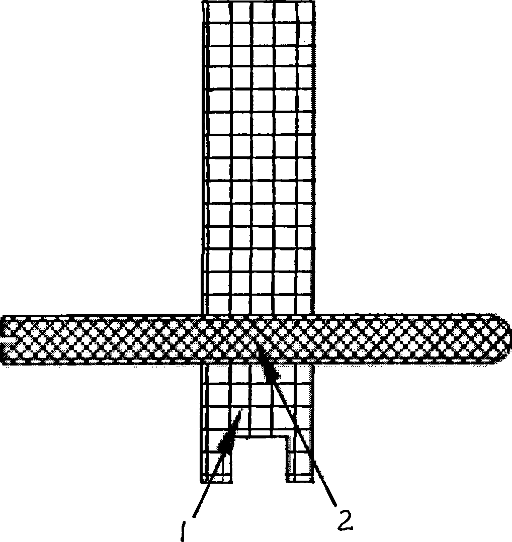
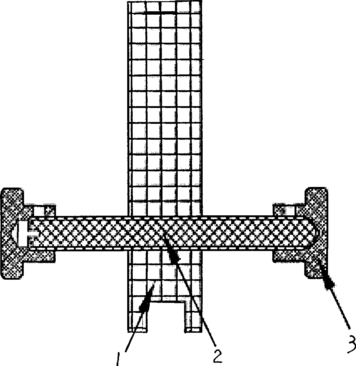
[0028] see figure 1 , figure 2 , The filter coupling structure of the present invention includes a support 1 , an M3 adjusting screw 2 , or two flanges 3 .

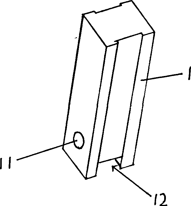
[0029] see image 3 , the support member 1 among the present invention is made of PTFE material, is a rectangular columnar structure, its lower part is provided with the screw hole 11 that runs through two opposite sides, and the side and the bottom surface of the other two without screw holes are provided with the groove 12 that installs. .

[0030] The M3 adjusting screw 2 is made of brass silver-plated material, which passes through the screw hole 11 of the support and is connected to the lower part of the support.

[0031] The two flanges 3 are made of brass silver-plated material, which are respectively connected to the two ends of the M3 adjusting screw to form a dumbbell-shaped structure.

[0032] Figure...


PUM


Abstract

The invention provides a filter coupling structure, which comprises a support, an M3 adjusting screw, or two flanges. A screw hole through two opposite sides is formed on the lower part of the support; the M3 adjusting screw penetrates the screw hole of the support and is connected with lower part of the support; and the two flanges are respectively connected with both ends of the M3 adjusting screw to form a dumbbell-like structure. Compared with the prior, the filter coupling structure has good product consistency, stability and reliability.

Description

technical field [0001] The invention relates to a filter in the field of wireless communication, in particular to a capacitive cross-coupling structure for a coaxial cavity filter. Background technique [0002] With the rapid development of wireless communication systems, the requirements for system quality are also continuously increasing. In order to prevent interference from other signals in the required frequency band, improve the utilization rate of the frequency band. System operators are increasingly demanding filter performance. [0003] The 1 / 4 wavelength coaxial cavity filter is used as a distributed parameter element, and the capacitive coupling of lumped parameters is used to form a bandpass filter. According to the technical indicators of the filter involved, the type, number of stages, and structure of the filter are determined; For the cross-coupling with steep out-of-band characteristics, the four-cavity cross-coupling and three-cavity cross-coupling forms a...

Claims


Application Information

Patent Timeline
Patent Type & Authority Applications(China)
IPC IPC(8): H01P5/00
Inventor 边登峰廉嘉乐史作毅韩元清
Owner ALLRIZON TONGGUANG COMM EQUIP SHANGHAI
Why Eureka
Try Eureka