Filter element

A technology of filter element and receiving part, which is applied in the direction of filtration separation, engine element, separation method, etc., can solve the problem of expensive modification of electric heater, etc., and achieve the effect of cheap heating

Inactive Publication Date: 2009-07-08
ALBONAIR GMBH
View PDF0 Cites 1 Cited by
  • Summary
  • Abstract
  • Description
  • Claims
  • Application Information

AI Technical Summary

Problems solved by technology

[0004] The disadvantage here is that electrical energy is required for heating
Furthermore, it is disadvantageous that replacement either entails an expensive ...

Method used


Image

  • Filter element
  • Filter element
  • Filter element

Examples


no. 1 approach

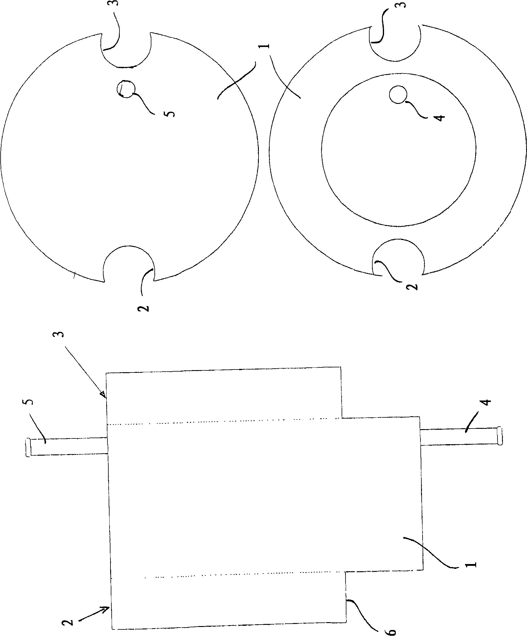
[0029] The filter element 1 has two grooves 2 and 3 on the outer side along its longitudinal extension, ie in a direction parallel to the central axis. The coolant hoses of the internal combustion engine can be inserted or snapped into the grooves 2 and 3 of the filter element 1 .

[0030] The filter element 1 is heated by means of the coolant hoses, not shown, snapped into the grooves 2 and 3 and prevents the liquid to be filtered from freezing.

[0031] The filter element 1 has two pipe connections 4 and 5 which serve as inflow and outflow for the liquid to be filtered.

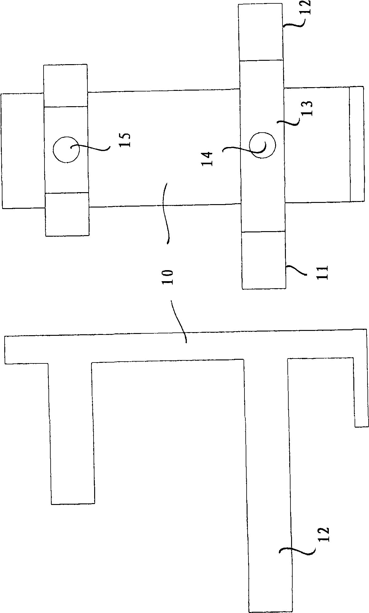
[0032] The filter element 1 is designed asymmetrically and has a shoulder 6, so that the filter element 1 can only be mounted in a unique position figure 2 corresponding bracket 10. according to figure 2 The support 10 has two projections 11 and 12 in the lower part for this purpose.

[0033] Between the two projections 11 and 12 on which the shoulder 6 of the filter element 1 rests, the support has a...


PUM


Abstract

The invention relates to a filter element (1, 21) which is particularly used for filtering a liquid to be solidified and is particularly used for filtering a reducing agent for selective catalyctic reduction in an exhaust after-treatment device of an internal-combustion engine, wherein the filter element (1, 21) is provided with at least one gap (2, 3) and/or a containing part (22, 23). A pipeline heating the filter element (1, 21) is inserted or can be inserted into the gap and/or the containing part, wherein the pipeline guides the fluid with increased temperature so that the filter element (1, 21) can form a radiator.

Description

technical field [0001] The invention relates to a filter element, in particular for filtering a liquid to be solidified, in particular for filtering a reducing agent for selective catalytic reduction in an exhaust gas aftertreatment device of an internal combustion engine. Background technique [0002] In order to reduce nitrogen oxides in the exhaust gases of combustion plants, waste combustion plants, industrial plants and engines, ammonia or ammonia solutions such as so-called AdBlue are mixed into the exhaust gases. AbBlue is a synthetic 32.5% urea solution according to DIN 70070 for aftertreatment of exhaust gases in SCR catalytic converters. Here, nitrogen oxides (NOx) are reduced by approximately 90% by selective catalytic reduction (SCR). x ) emissions. Urea solutions such as AdBlue freeze at about -11°C. In order to ensure the operation of the metering system for injecting urea solutions such as AdBlue into the exhaust gas even at temperatures below this, system ...

Claims


Application Information

Patent Timeline
IPC IPC(8): B01D35/18B01D35/02F01N3/28B01D53/94
CPCF01N2240/02F01N3/2066Y02T10/24F01N2610/1406F01N2610/02Y02T10/12
Inventor D·布莱克S·阿德勒
Owner ALBONAIR GMBH
Why Eureka
Try Eureka