
Method for processing light rail conductive bus-bar wire end welding beveling machine and processing equipment

A technology of welding grooves and busbars, applied in the field of machining, can solve the problems of difficult processing of welding grooves 11 at the end, low efficiency, and difficult clamping due to workpiece movement, and achieve simple processing equipment, easy operation, and improved processing efficiency effect

Inactive Publication Date: 2009-07-08
赵俊
View PDF0 Cites 7 Cited by
  • Summary
  • Abstract
  • Description
  • Claims
  • Application Information

AI Technical Summary

Problems solved by technology

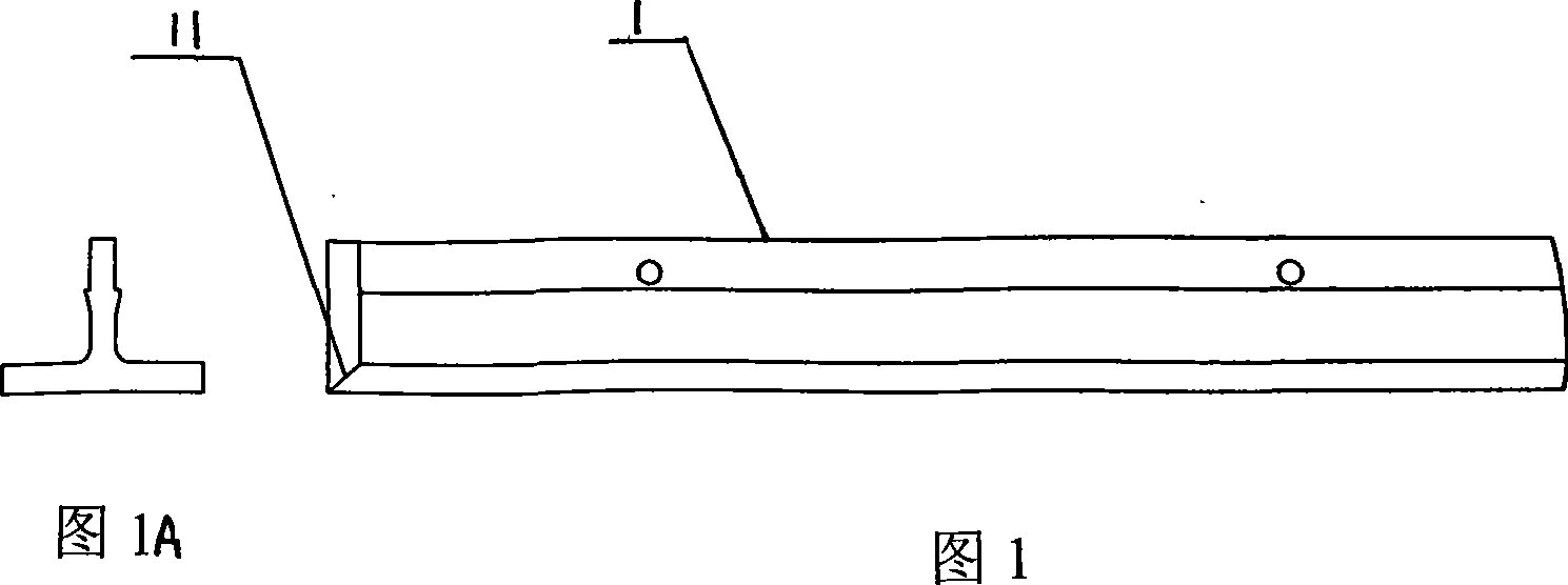
The basic structural shape of the conductive bus bar 1 is shown in Fig. 1, Fig. 1A and Figure 1B , because the length of each conductive bus bar is long (more than about 10 meters), the processing of the end welding groove 11 is very difficult. The existing method is to use a common milling machine or boring machine to process, and the workpiece is moved to complete the processing. It is too long and needs to be moved, so it is difficult to clamp and low in efficiency, and manual grinding cannot meet the needs

Method used


Image

  • Method for processing light rail conductive bus-bar wire end welding beveling machine and processing equipment
  • Method for processing light rail conductive bus-bar wire end welding beveling machine and processing equipment
  • Method for processing light rail conductive bus-bar wire end welding beveling machine and processing equipment

Examples


Embodiment Construction

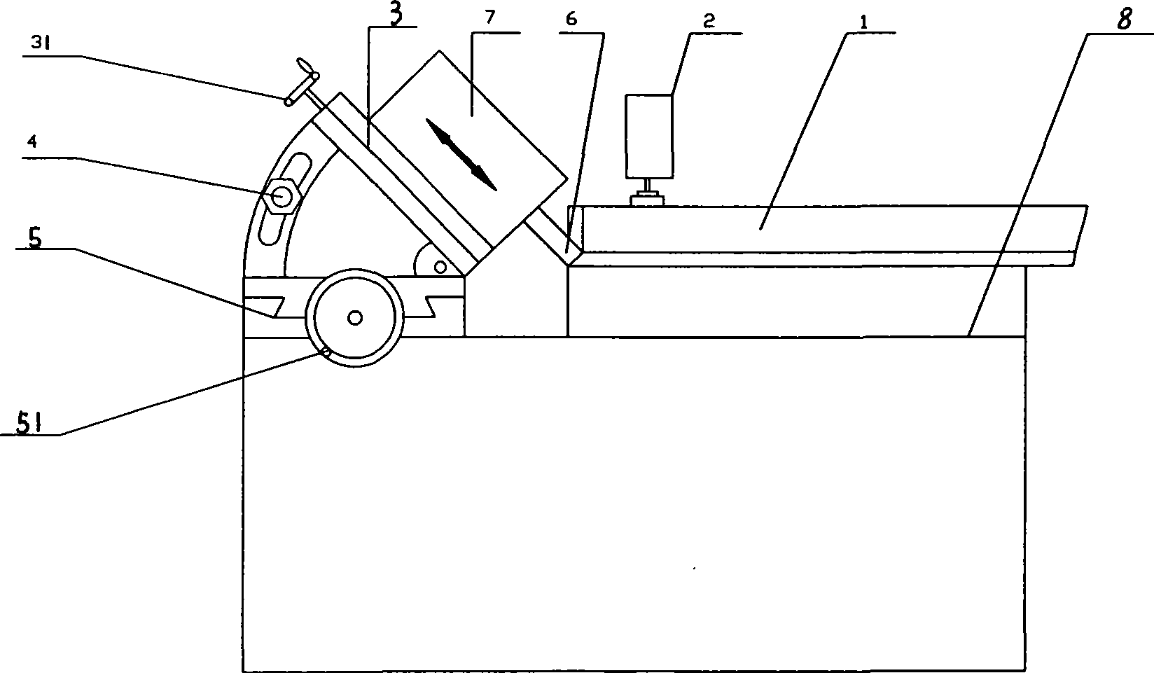
[0014] see figure 2 , Conductive busbar bevel processing equipment is composed of workbench 8, pressing device 2 and milling machine installed on the workbench. The milling machine is composed of a milling cutter 6, a milling head 7, a feed mechanism 3 and a cutter mechanism 5. The milling cutter 6 is clamped on the drill holder of the milling head 7, and the milling head 7 is installed on the feed mechanism 3. The milling head 7 is rotated by a built-in motor and drives the milling cutter to rotate for cutting. The feeding mechanism 3 and the knife-feeding mechanism 5 are respectively driven by the feed handle 31 and the knife-feeding handle 51 to which they belong, and the screw is rotated, and the rotary motion is converted into the linear motion of the mechanism through the nut. The feeding mechanism 3 is installed on the slide plate of the knife-feeding mechanism 5 Each is responsible for feed and retreat in one direction. The angle of the feed mechanism 3 is changed b...


PUM


Abstract

The invention proposes a processing method for a light rail electric cylinder manifold end jointing beveling machine and processing equipment thereof. The method is as follows: compressing and positioning the electric cylinder manifold on a machine table by utilizing a compressor; firstly, based on the angle of the electric cylinder manifold end jointing beveling which is needed for processing, changing milling head to a needed angle by regulating the adjusting nut of the milling machine; then wheeling the feed lever of the milling machine to control the feed movement of the milling cutter, and wheeling the tool moving lever to control tool movement, thus the process of the divided edge is completed by moving the milling head. The processing method of the invention improves the processing efficiency greatly, in addition, the processing equipment is simple and easy to operate.

Description

technical field [0001] The invention belongs to machining technology, and in particular relates to a machining method for a conductive bus bar of a light rail. Background technique [0002] With the attention of automobile exhaust emissions all over the world, rail transit has been vigorously developed. Most of the power of rail transit comes from the power grid and is transmitted to rail locomotives through conductive bus bars. The conductive bus bars are connected into two by welding. Set of conductive loops (locomotive back and forth two-way loop), so the use of conductive busbars is increasing, which is four times that of locomotive running lines. The basic structural shape of the conductive bus bar 1 is shown in Fig. 1, Fig. 1A and Figure 1B , because the length of each conductive bus bar is long (more than about 10 meters), the processing of the end welding groove 11 is very difficult. The existing method is to use a common milling machine or boring machine to process...

Claims


Application Information

Patent Timeline
Patent Type & Authority Applications(China)
IPC IPC(8): B23C3/12B23Q3/06B23Q5/34
Inventor 赵俊
Owner 赵俊
Learn More