Blast furnace iron manufacturing process

A blast furnace ironmaking and blast furnace technology, which is applied in blast furnaces, blast furnace details, furnaces, etc., can solve the problems of low strength of blue carbon and cannot replace coke, and achieves the improvement of furnace body reduction, the reduction of the burden of transitional utilization, and the reduction of production costs. Effect

Inactive Publication Date: 2009-07-08
BEIJING ZHONGDIAN HUAFANG TECH +1
View PDF0 Cites 16 Cited by
  • Summary
  • Abstract
  • Description
  • Claims
  • Application Information

AI Technical Summary

Problems solved by technology

However, due to the low strength of semi-coke, it cannot completely replace coke in the blast furnace ironmaking process

Method used


Image

  • Blast furnace iron manufacturing process
  • Blast furnace iron manufacturing process

Examples


Embodiment Construction

[0026] In order to further illustrate the principle and structure of the present invention, the preferred embodiments of the present invention are now described in detail in conjunction with the accompanying drawings, but the embodiments are only for illustration and explanation, and cannot be used to limit the scope of patent protection of the present invention.

[0027] The blast furnace ironmaking method provided by the invention uses semi-coke to replace part of the coke, and can reduce the amount of coke used in the blast furnace ironmaking under the condition that the ironmaking process is normally carried out.

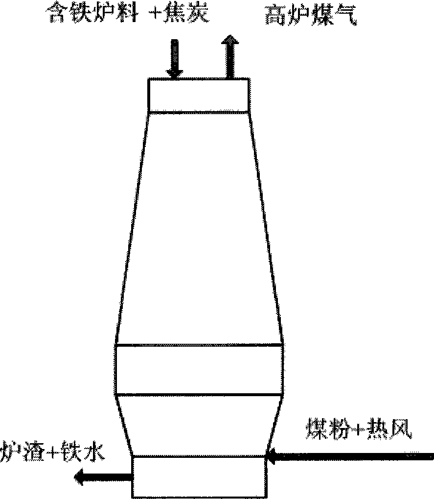
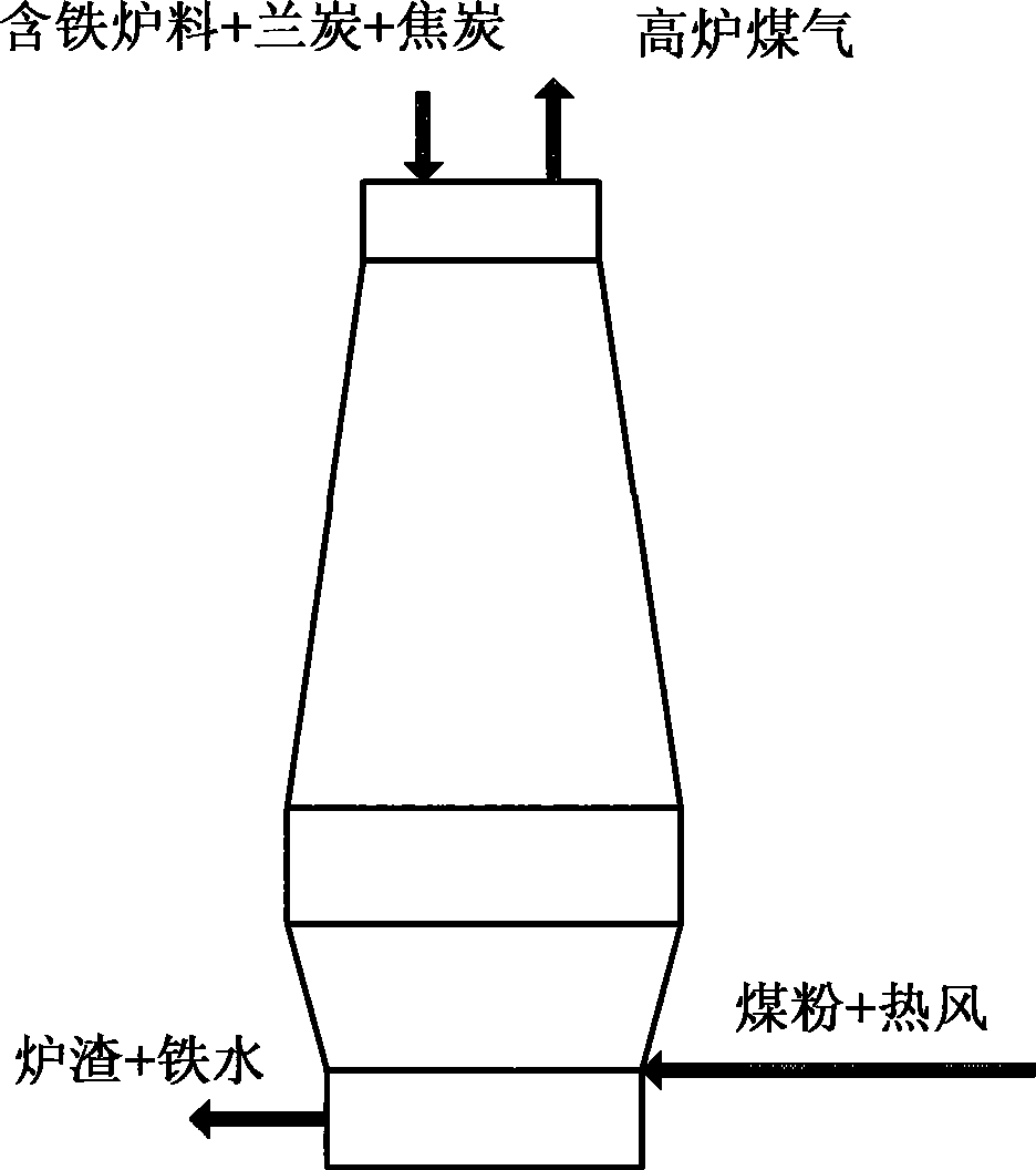
[0028] figure 2 The basic smelting process of the blast furnace ironmaking method of the present invention is shown. see figure 2 , according to the blast furnace ironmaking method of the present invention, comprising a first step and a second step.

[0029] In the first step, coke and semicoke and other iron-containing charge are charged into the blast furn...


PUM


Abstract

The present invention provides a blast furnace iron-smelting method, including: a first step, loading coke, semi-coke and other iron-contained charging stock into the blast furnace, wherein, the semi-coke has a scheduled weight ratio in the coke and semi-coke; and a second step, performing conventional iron-smelting operations after the loading. The method can use semi-coke to replace part of coke, thus can reduce the amount of coke in the blast furnace iron-smelting process.

Description

technical field [0001] The invention relates to a blast furnace ironmaking method, in particular to a blast furnace ironmaking method in which semi-coke is used to replace part of coke as furnace fuel in the blast furnace ironmaking process. Background technique [0002] Generally speaking, the basic process of blast furnace ironmaking is the reduction process of iron, that is, using coke as fuel and reducing agent to convert iron ore or other non-iron oxides from oxide or mineral state (such as Fe2O3, Fe3O4 , Fe2SiO4, Fe3O4 · TiO2, etc.) reduced to liquid pig iron. [0003] Generally speaking, during blast furnace ironmaking, the blast furnace is divided into five working areas from top to bottom: massive zone, soft melting zone, dripping zone, roundabout zone, and slag-iron accumulation zone. Melt bands, and blocky bands gradually decrease upwards. [0004] figure 1 The basic smelting process of traditional blast furnace ironmaking is shown. [0005] refer to figure 1...

Claims


Application Information

Patent Timeline
Patent Type & Authority Applications(China)
IPC IPC(8): C21B5/00
Inventor 杨岩张建良王群力杨天钧国宏伟郭豪
Owner BEIJING ZHONGDIAN HUAFANG TECH
Why Eureka
Try Eureka