Novel steam generation apparatus and use thereof

A technology of a steam generating device and a steam generator, which is applied in steam generation, steam generation methods, applications, etc., can solve the problems of unsafety, small steam outlet channel of heating element, and high cost, and achieve long service life, clean steam, and low cost. cheap effect

Inactive Publication Date: 2009-07-08
张贵超 +1
View PDF0 Cites 15 Cited by
  • Summary
  • Abstract
  • Description
  • Claims
  • Application Information

AI Technical Summary

Problems solved by technology

[0004] The disadvantages of this method are: (1) The steam outlet of the heating element is large, the steam in the heating body has no pressure, and the steam sandwiched with water is not fully vaporized in the heating body, so it is sprayed from the steam outlet to the working surface, and high temperature cannot be obtained. Dry steam; (2) The chemical preparations in the heating body will be sprayed to the working surface with the steam and pollute the working surface due to the loose fixation; (3) Steam with a certain pressure cannot be obtained
[0005] (2) The steam outlet channel of the heating body is small, the pressure steam in the heating body is greater than 1 steam pressure, the pressure in the water tank is 1 steam pressure, which is smaller than the steam pressure in the heating body, and there is no steam return pipe, so that the water tank The internal pressure and the pressure of the heating body are balanced, so that the water in the water tank cannot enter the heating body through the weight of the water, and can only be pumped into the heating body by hand pumps, electric pumps, electromagnetic pumps, etc.
[0008] The disadvantages of this method are: (1) the internal pressure of the sealed boiler is too large, which is extremely unsafe; (2) the cost is relatively high

Method used


Image

  • Novel steam generation apparatus and use thereof
  • Novel steam generation apparatus and use thereof
  • Novel steam generation apparatus and use thereof

Examples


Embodiment 1

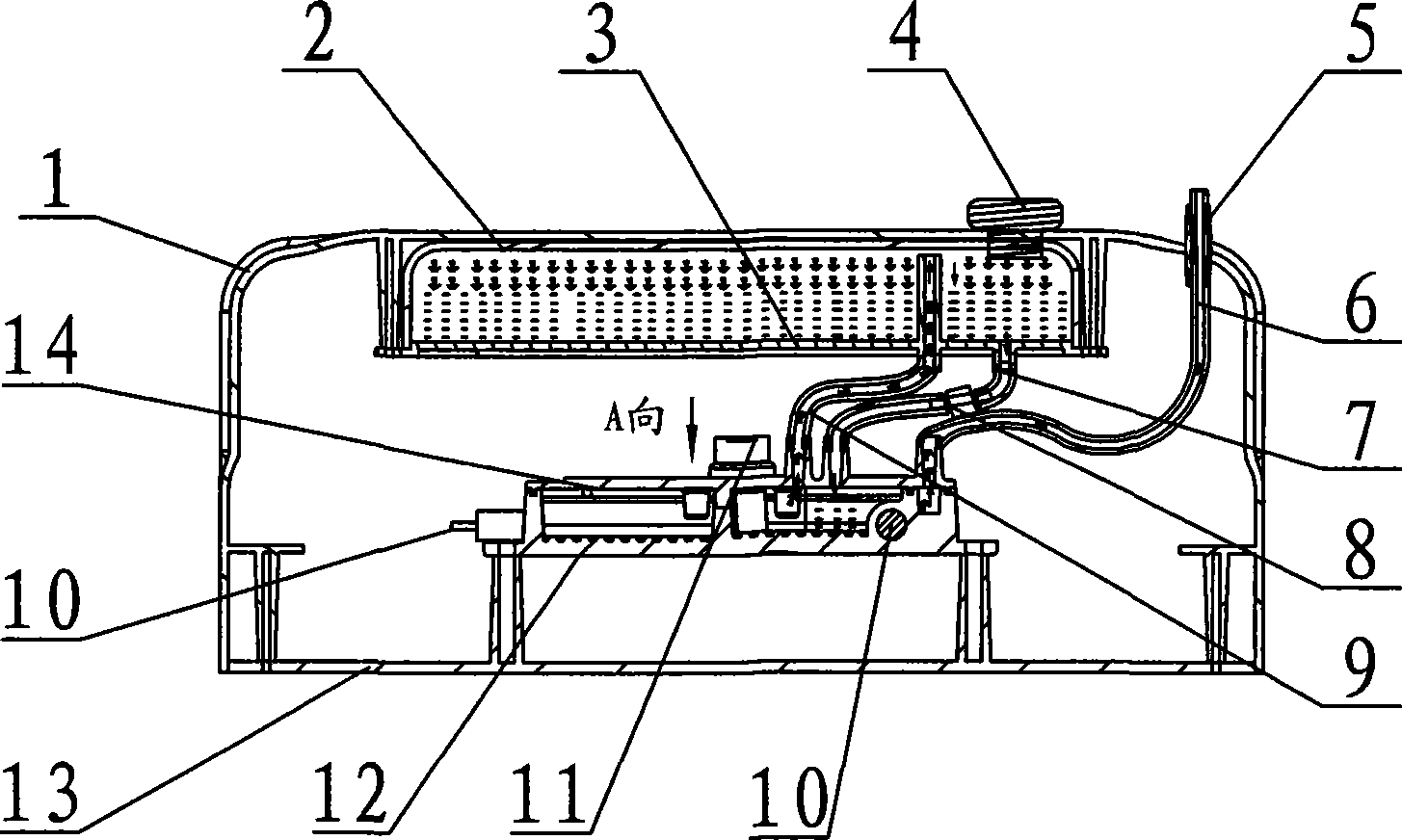
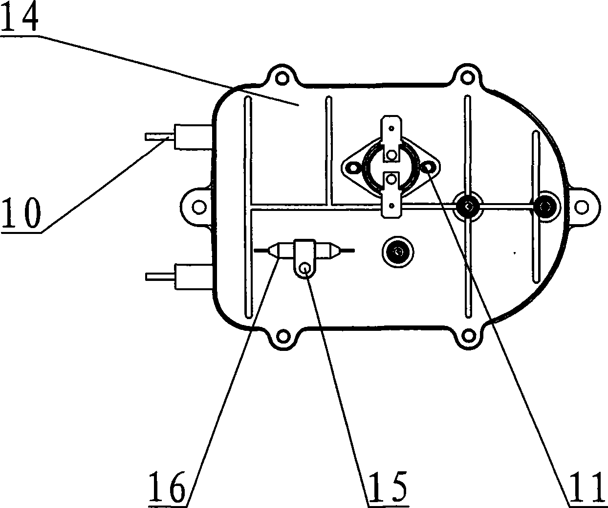
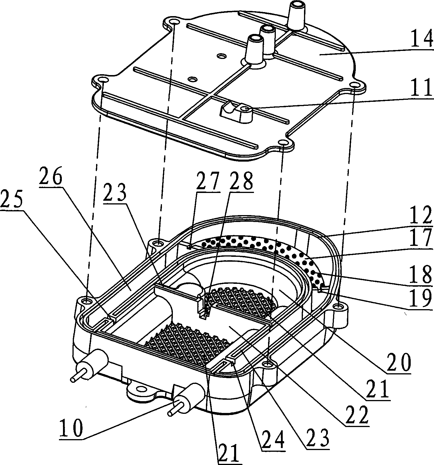
[0035] Embodiment 1 is applied to the steam mop, such as Figure 4-Figure 5 As shown, the handle 29 of the ground mop is connected to the base 1 of the steam generating device, the cleaning cloth 30 is installed below the cover plate 13, and the water tank and the heating element are arranged in the shell formed by the base and the cover plate. The steam return pipe 9 and the water inlet pipe 7 controlled by the control valve 8 are connected between them, and the steam output pipe 6 is connected to the shell cover plate by the steam cover 14 of the heating element and leads to the cleaning cloth 30 through the floor mop base. When the control valve 8 on the water inlet pipe 7 is opened, water flows into the first vaporization chamber 20 of the heating element by its own weight, and the heated heating element turns hydration into water vapor, and forms steam at a certain pressure in the first vaporization chamber. Part of it enters the second vaporization chamber 22 and then en...

Embodiment 2

[0036] Embodiment 2 is applied to a hand-held steam cleaner, such as Figure 6 As shown, a water tank and a heating element are installed in the cleaning machine housing 31, and a steam return pipe 9 and a water inlet pipe 7 with a control valve 8 are connected between the water tank and the heating element, and between the nozzle 32 and the heating element The steam output pipe 6 is connected to output the steam to the working surface. Since the steam return pipe 9 is set between the water tank and the heating element, when the control valve 8 installed on the water inlet pipe 7 is opened, the water flows into the heating element by its own weight. A vaporization chamber 20, the heated steam converts water into water vapor, forms steam at a certain pressure in the first vaporization chamber, and part of the steam enters the second vaporization chamber 22 and then enters the third vaporization chamber 26, with a certain pressure and high temperature The dry steam enters the work...

Embodiment 3

[0037] Embodiment 3 is applied to a steam iron, such as Figure 7 As shown, a steam output pipe 6 is connected between the iron assembly 33 and the steam generating device, and the steam is input to the iron assembly, and sprayed to the working surface after heating. Since the steam return pipe 9 is connected between the water tank and the heating element, when the When the control valve 8 on the water inlet pipe 7 is installed, the water flows into the first vaporization chamber 20 of the heating element by its own weight, and the heated steam turns the water into water vapor and forms steam with a certain pressure in the first vaporization chamber, and part of the steam enters the second vaporization chamber. The steam chamber 22 then enters the third vaporization chamber 26 to form high-temperature dry steam with a certain pressure, and enters the working surface through the steam output pipe 6 and then the iron assembly 33, and another part of the steam flows back to the wa...


PUM


Abstract

The invention relates to a novel steam generating device and application thereof. The inside of a shell of the device is provided with a sealing water tank provided with a water inlet plug and a steam generator, wherein the inside of a heating shell of the steam generator is provided with a heating pipe, a plurality of evaporating chambers which are separated by separating plates and communicated through steam outlet channels, and a steam outlet chamber which is communicated with the last evaporating chamber and provided with steam outlet holes. The cross section area of each steam outlet channel between the evaporating chambers and between the evaporating chamber and the steam outlet chamber is between 2 and 5 square millimeters, and the steam is output to a working surface by a steam output pipe. A water inlet pipe and a steam return pipe which are controlled by a control valve are arranged between the water tank and a heating body, wherein the steam return pipe introduces high pressure steam in the heating body into the water tank by one path so as to ensure that the pressure in the water tank and the pressure in the heating body are balanced, and the water can enter the heating body by deadweight. The device has the advantages that: (1) the heating evaporation adopts a physical theory, and chemical preparations do not need to be added, thereby having the advantages of simple process, reliability, clean steam, environmental protection, convenient use and high efficiency; (2) an ultrathin heating evaporation device can be adopted, and applied to homes and other places difficult to be cleaned by tools; and (3) the power of the steam generator is cyclically driven by self, and has the advantages of low cost, no noise, safety and long service life. The device can be applied to electric appliance products, such as steam mops, hand-hold type cleaners, steam irons, and the like.

Description

technical field [0001] The invention relates to a novel steam generating device for turning water into steam and its application in electrical appliances using steam. Background technique [0002] Currently used in household electric irons, industrial electric irons, garment steamers, hand-held steam cleaners, steam floor mops, multi-function steamers, etc., to vaporize water into steam, there are usually the following three methods: [0003] (1) The steam outlet channel of the heating element is relatively large, and there is no pressure steam in the heating body which is less than 1 steam pressure. The pressure in the water tank is 1 steam pressure and the steam pressure in the heating body is balanced. The water in the water tank passes through the The water enters the heating body by its own weight, and the water in the heating body is dispersed by a chemical agent to generate heat and vapor, which is vaporized into water vapor by heating, and is sprayed out to the worki...

Claims


Application Information

Patent Timeline
Patent Type & Authority Applications(China)
IPC IPC(8): F22B1/28A47L13/22A47L11/34B08B3/00D06F75/06
CPCA47L13/225
Inventor 张贵超匡柳
Owner 张贵超
Why Eureka
Try Eureka