Electric power plant condenser ball cleaning on-line monitoring device based on optical fiber sensing technology

The invention relates to an optical fiber sensing technology and a monitoring device technology, which is applied to the field of on-line monitoring devices for cleaning rubber balls of condensers in power plants, and can solve the problems of difficulty in inspecting and recovering rubber balls to detect wear of rubber balls, high purchase price of cleaning systems, and increased manufacturing costs. Achieving the best cleaning effect, light weight and less space occupation

Inactive Publication Date: 2009-07-08
SHENYANG INST OF ENG
View PDF2 Cites 14 Cited by
  • Summary
  • Abstract
  • Description
  • Claims
  • Application Information

AI Technical Summary

Problems solved by technology

Even so, because the products of these two companies are sold as a complete set in our country, and they do not sell components such as automatic rubber ball recovery monitors or flapping rubber ball filters, not only the purchase price of the entire cleaning system is quite expensive, but also the power plant Also had to replace the original rubber ball cleaning system that had not completely failed, resulting in a huge waste of resources
[0006] The inventor once aimed at problems such as checking the number of recycled rubber balls and detecting rubber ball wear in the prior art, and replacing a complete set of cleaning equipment will cause resource waste, etc., and designed the "Automatic Monitoring...

Method used


Image

  • Electric power plant condenser ball cleaning on-line monitoring device based on optical fiber sensing technology
  • Electric power plant condenser ball cleaning on-line monitoring device based on optical fiber sensing technology
  • Electric power plant condenser ball cleaning on-line monitoring device based on optical fiber sensing technology

Examples


Embodiment Construction

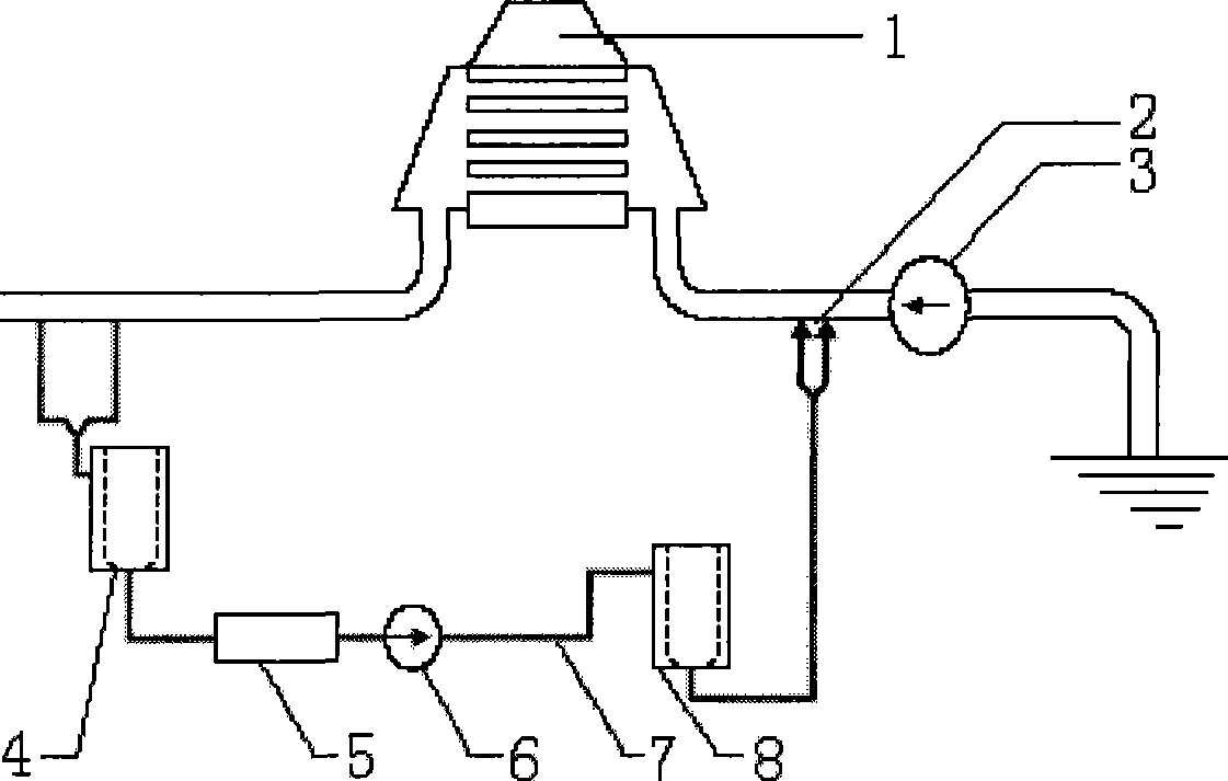
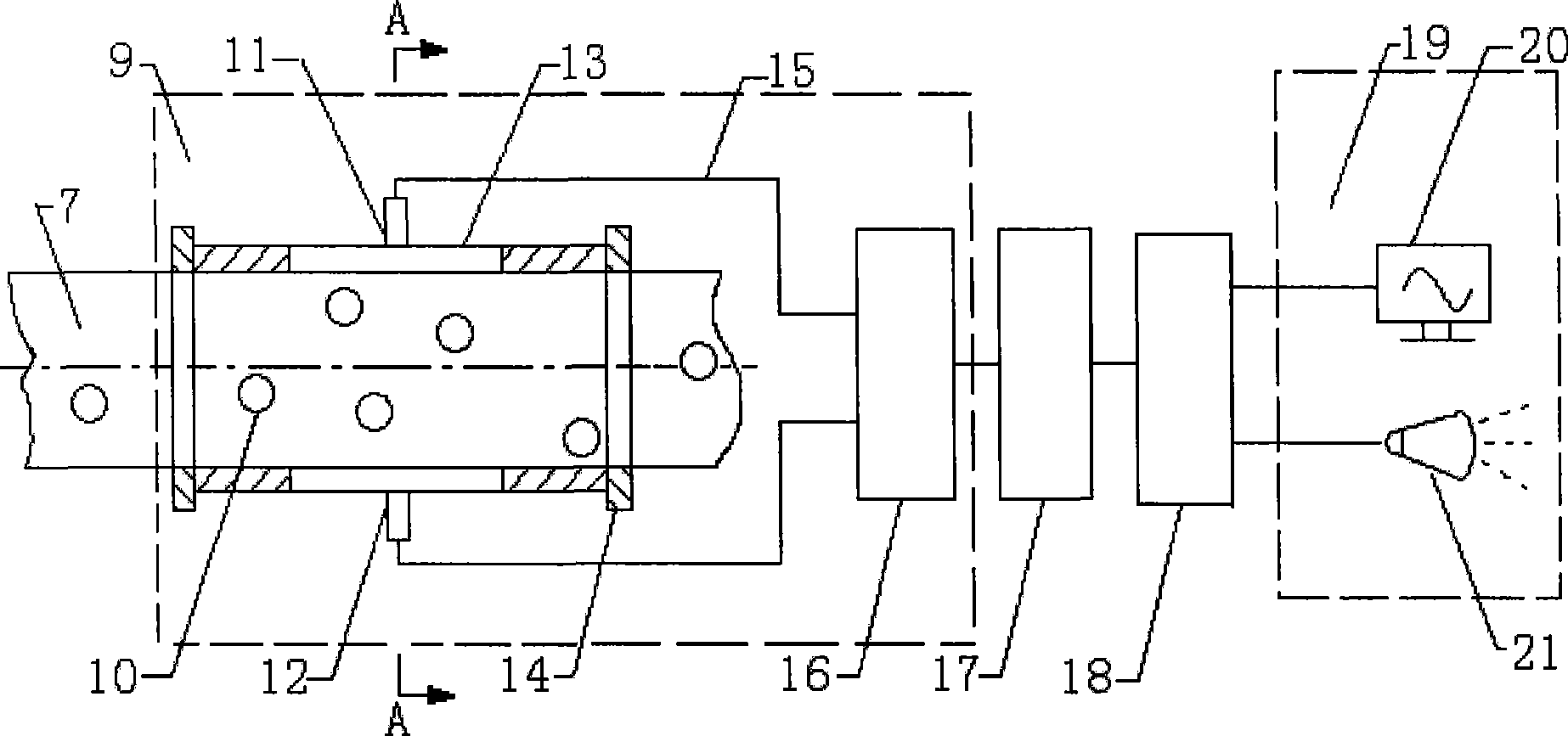
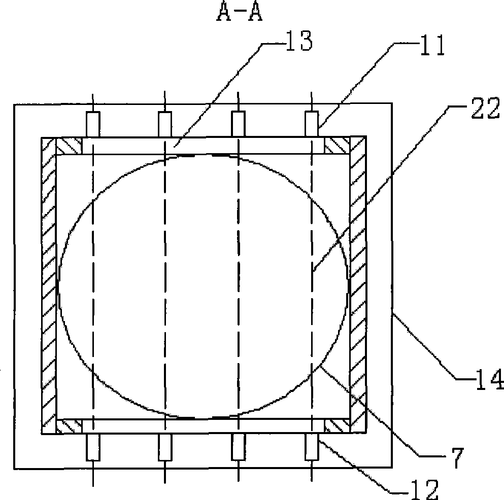
[0016] according to figure 1 The specific structure of the present invention will be described in detail with the embodiments. The on-line monitoring device for cleaning rubber balls in a power plant condenser based on optical fiber sensing technology includes a monitoring device 5 connected to a rubber ball circulation pipeline of the rubber ball cleaning device and a monitoring control circuit thereof. Such as figure 1 As shown, the rubber ball cleaning device of the condenser 1 is composed of a rubber ball nozzle 2, a circulating water pump 3, a ball collecting chamber 4 with a ball collecting net, a monitoring device 5, a rubber ball pump 6, a rubber ball conveying pipeline 7, a ball loading Room 8 and so on. The monitoring device 5 is used as an additional part of the rubber ball cleaning device, and its housing is connected in the rubber ball circulation pipeline of the rubber ball cleaning device through flanges 14 at both ends. In this embodiment, in order to ensure...


PUM


Abstract

The invention relates to an on-line monitoring device for rubber ball cleaning of a condenser of a power plant based on optical fiber sensing technology. The device comprises a rubber ball cleaning device and a monitoring control circuit. The technical key points of the device comprise: an information acquisition unit of the monitoring control circuit adopts a contrast type optical fiber photoelectric sensor, a transmitting end and a receiving end of the contrast type optical fiber photoelectric sensor are packaged on the relative positions at both sides of a shell of the monitoring device respectively, planes where axes of the transmitting end and the receiving end are positioned are perpendicular to a water flow direction in the shell, the contrast type optical fiber photoelectric sensor is connected with a computer data analysis and processing unit of the monitoring control circuit through a switching value input board, and an output end of the computer data analysis and processing unit consisting of a data acquisition and storage module and a statistic data analysis module is connected with an alarm display unit. The device is used as an additional component of the rubber ball cleaning device. Compared with the prior similar devices, the device has a simple structure and low cost, and can monitor the quantity of rubber balls recovered in a circulating pipeline in a real-time, on-line and accurate mode.

Description

technical field [0001] The invention relates to an automatic monitoring device based on optical fiber sensing technology, in particular to an optical fiber-based sensor used as an independent additional component for real-time on-line detection of the number of recovered rubber balls in the circulation pipeline of a rubber ball cleaning device for a power plant condenser. Power plant condenser rubber ball cleaning online monitoring device based on sensor technology. Background technique [0002] As we all know, during the power generation process, the power plant mainly uses the rubber ball cleaning device to clean the condenser to prevent the dirt on the cooling tube wall of the condenser from affecting the heat exchange efficiency of the condenser, resulting in a decrease in the vacuum degree of the unit and increasing the coal consumption of power generation. If fouling occurs on the pipe wall, it will seriously affect the normal operation of the cleaning device. The exi...

Claims


Application Information

Patent Timeline
IPC IPC(8): F28G1/12
Inventor 李智郑维平王祥凤
Owner SHENYANG INST OF ENG
Why Eureka
Try Eureka