Electric transformer winding and iron core fixing device

A technology for fixing power transformers and iron cores, which is applied in the directions of transformer/inductor cores, transformer/inductor coils/windings/connections, etc. Uneven force and other problems, to achieve the effect of reducing no-load current, improving no-load performance, and strong applicability

Inactive Publication Date: 2009-07-08
常德国力变压器有限公司
View PDF0 Cites 4 Cited by
  • Summary
  • Abstract
  • Description
  • Claims
  • Application Information

AI Technical Summary

Problems solved by technology

Due to the tight clamping of the two ends of the iron yoke and the looseness in the middle, the clamped channel steel is curved, and the force on the iron yoke is uneven. The tension between the channel steel and the iron yoke (mostly without weft Glass ribbons or steel strips) are mostly useless in practical applications; although the core-piercing screw structure solves the problem of uniform force on the iron yoke, the effective section of the iron yoke becomes smaller due to the tightening of the iron yoke punching screw, especially when the magnetic flux Distortion occurs when passing through the punching part, which directly affects the quality of power supply
At the same time, the common disadvantages of the above two structures are that the noise of the power transformer increases and the no-load performance decreases.

Method used


Image

  • Electric transformer winding and iron core fixing device
  • Electric transformer winding and iron core fixing device
  • Electric transformer winding and iron core fixing device

Examples


Embodiment Construction

[0011] Now in conjunction with the accompanying drawings, the technical content of the present invention is described in detail.

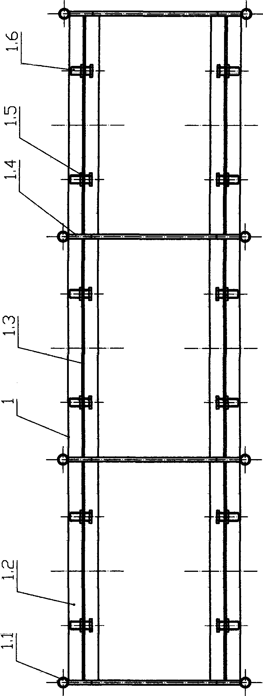
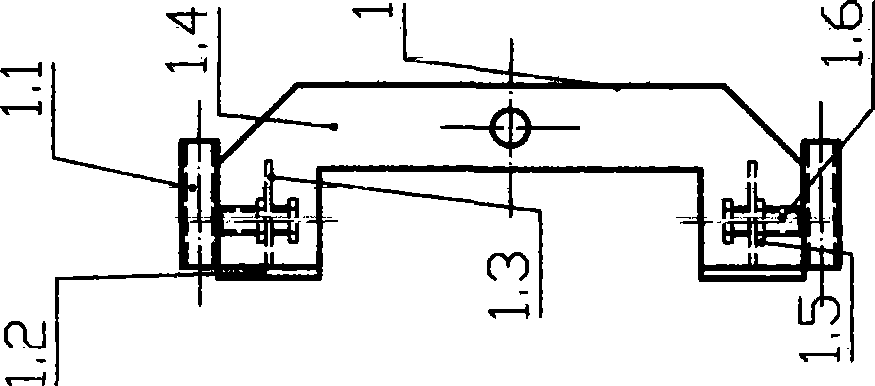
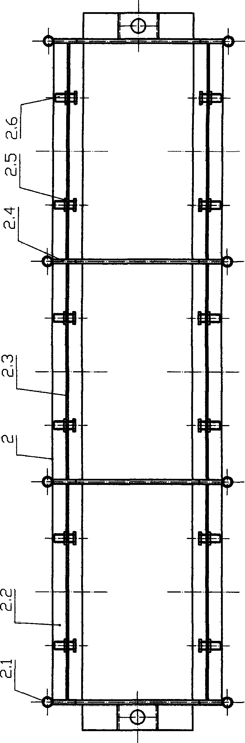
[0012] The two ends of the 4 bow-shaped upper pressure plates (1.4) of the upper clamp (1) are respectively welded to the 4 sets of upper steel pipes (1.1), and the upper top plate (1.2) and the upper fixing plate (1.3) are T-shaped welded and connected to the upper The pressing plate (1.4) is connected as a whole; several sets of upper threaded assemblies composed of upper nuts (1.5) and upper bolts (1.6) are connected with the upper fixing plate (1.3); the four bow-shaped lower pressing plates (2.4) of the lower clamp (2) ) are respectively welded to 4 sets of lower steel pipes (2.1), the lower top plate (2.2) and the lower fixing plate (2.3) are welded in a T-shape and connected to the lower pressure plate (2.4) as a whole, and the lower nut (2.5) Several groups of lower thread assemblies formed with lower bolts (2.6) are connected with the lowe...


PUM


Abstract

A device for fixing a power transformer winding and an iron core consists of an upper fixture and a lower fixture with same structures. Through the reasonable regulation of arrays of screw-thread components, the uniform and effective clamping of an iron yoke is ensured, thereby overcoming the drawbacks that the stress of the iron yoke with a channel iron and teartape structure is not uniform, and the teartape is almost nonexistent; the effective cross section of the iron yoke with a core-passing screw rod structure becomes smaller, and the magnetic flux distorts; the noise is big; and the no-load capacity is reduced. The device have the advantages of reasonable design, simple structure, no-load property improvement due to timely adjustment of the clamping force of the iron yoke, obvious noise reduction function, convenient manufacture and regulation, good adaptability, high spread and application values, and remarkable socio-economic benefits.

Description

technical field [0001] The invention relates to a power transformer assembly, in particular to a power transformer winding and iron core fixing device. Background technique [0002] At present, the winding compression, iron core clamping and body positioning of power transformers generally adopt the following two structures: channel steel pull belt and core screw. Due to the tight clamping of the two ends of the iron yoke and the looseness in the middle, the clamped channel steel is curved, and the force on the iron yoke is uneven. The tension between the channel steel and the iron yoke (mostly without weft Glass ribbons or steel strips) are mostly useless in practical applications; although the core-piercing screw structure solves the problem of uniform force on the iron yoke, the effective section of the iron yoke becomes smaller due to the tightening of the iron yoke punching screw, especially when the magnetic flux Distortion occurs when passing through the punching par...

Claims


Application Information

Patent Timeline
Patent Type & Authority Applications(China)
IPC IPC(8): H01F27/26H01F27/30
Inventor 肖健黄世付
Owner 常德国力变压器有限公司
Why Eureka
Try Eureka