Muller-c element

A component, M12 technology, applied in the field of electronic devices, can solve the problems of increased circuit complexity, unfavorable high-density digital design, increased integrated circuit area, etc., and achieve the effects of small propagation delay, good signal integrity, and increased speed

Inactive Publication Date: 2009-07-08
NXP BV
View PDF0 Cites 11 Cited by
  • Summary
  • Abstract
  • Description
  • Claims
  • Application Information

AI Technical Summary

Problems solved by technology

The disadvantage of this known architecture is that the inductor usually reaches a value of about 10nH to 100nH, which leads to a significant increase in the area of ​​the integrated circuit
If the inductor is provided externally to the integrated circuit, the complexity of the circuit increases and the reliability decreases
Accordingly, this approach is disadvantageous for high-density digital designs

Method used


Image

  • Muller-c element
  • Muller-c element
  • Muller-c element

Examples


Embodiment Construction

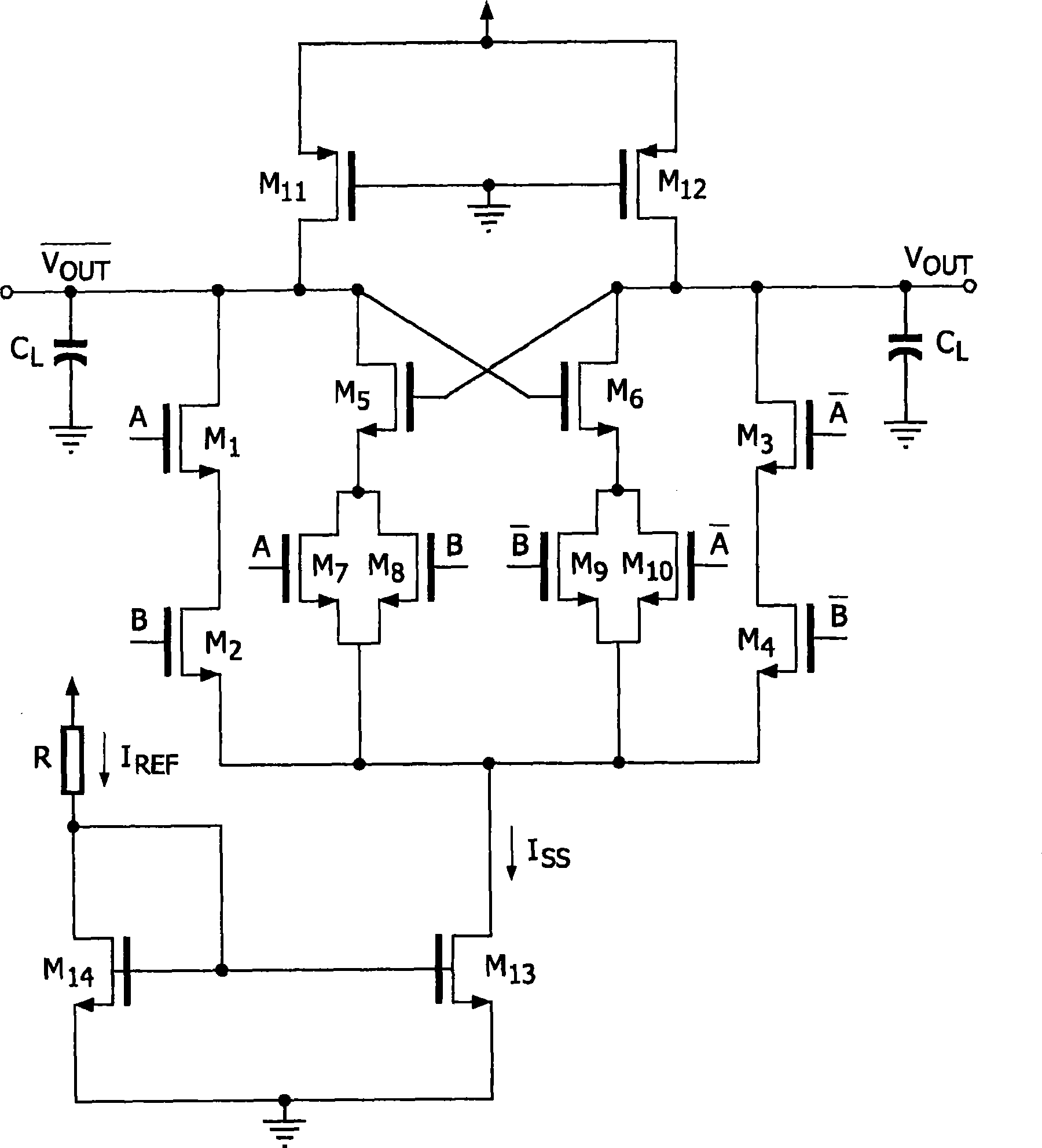
[0024]Figure 1 shows a prior art two-input MCML Muller-c element. The entire design is based on differential (symmetric) signal processing. It includes an NMOS differential network implementing Muller-c gate logic functions. The basic function is that of a current-steering switch. The MCML Muller-c element consists of two stages. The first differential stage acts as a transconductance to convert a differential input signal into an equivalent differential output current. The first stage mainly includes NMOS transistors M1 to M10. There is also a current mirror formed by NMOS transistors M13 and M14 to provide a current sink for the current Iss from the differential input stage, where the reference current I REF to bias the differential input stage. There is also a second differential stage formed by PMOS transistors M11 and M12. M11 and M12 are PMOS load transistors operating in the triode region. This second stage acts as a transimpedance to allow conversion of a curren...


PUM


Abstract

The invention relates to an electronic device that includes an MCML Muller-c element. The MCML Muller-c element has a first differential stage for operating in a trans- conductance state converting the differential input to a differential output current implementing the logical behavior of the MCML Muller-c element and a second stage operating as a trans-impedance stage being coupled to the first stage. Further, the MCML Muller-c element has peaking circuitry being coupled to the first stage, such that the peaking circuitry and the first stage provide a negative capacitance to the MCML Muller-c element for reducing the damping factor of the MCML Muller-c element.

Description

technical field [0001] The invention relates to an electronic device with MCML Muller-c elements. Background technique [0002] MOS Current Mode Logic (MCML) is conceived for high speed applications. The MCML topology is mainly used in CMOS transceivers for broadband communication circuits, first introduced by M.H.Aniss and M.I.Elmasry in "Self-timed MOS current mode logic for digital applications" in Proc.IEE Interpunct Conf.ASIC / SOC in 2002, pp .193-197.sonnet described in MCML to implement gigahertz MOS adaptive pipeline technology. The advantages of MCML circuits are lower voltage swing, higher operating frequency, and less electromagnetic coupling. Single-ended static circuits suffer from electromagnetic coupling. This aspect becomes even more relevant as chips scale down to nanoscale dimensions. Thus, CML provides differential (symmetric) signaling that makes circuits less susceptible to electromagnetic interference (EMI). [0003] The Muller-c element is named af...

Claims


Application Information

Patent Timeline
Patent Type & Authority Applications(China)
IPC IPC(8): H03K19/017H03K19/094
CPCH03K19/01806H03K19/20H03K19/01707
Inventor 苏哈斯·V·新德
Owner NXP BV
Why Eureka
Try Eureka