Electric discharge lamp device and lighting apparatus

A technology of lighting device and discharge lamp, applied in the field of lighting equipment and discharge lamp lighting device

Inactive Publication Date: 2009-07-08
PANASONIC CORP +1
View PDF1 Cites 4 Cited by
  • Summary
  • Abstract
  • Description
  • Claims
  • Application Information

AI Technical Summary

Problems solved by technology

[0014] However, the above Figure 8 The technique shown will cause the discharge lamp La to go out halfway, that is, although the discharge lamp La is lit during the first square wave operation FB2, the discharge lamp La is not lit during the subsequent high-frequency operation HF1.

Method used


Image

  • Electric discharge lamp device and lighting apparatus
  • Electric discharge lamp device and lighting apparatus
  • Electric discharge lamp device and lighting apparatus

Examples


no. 1 Embodiment approach

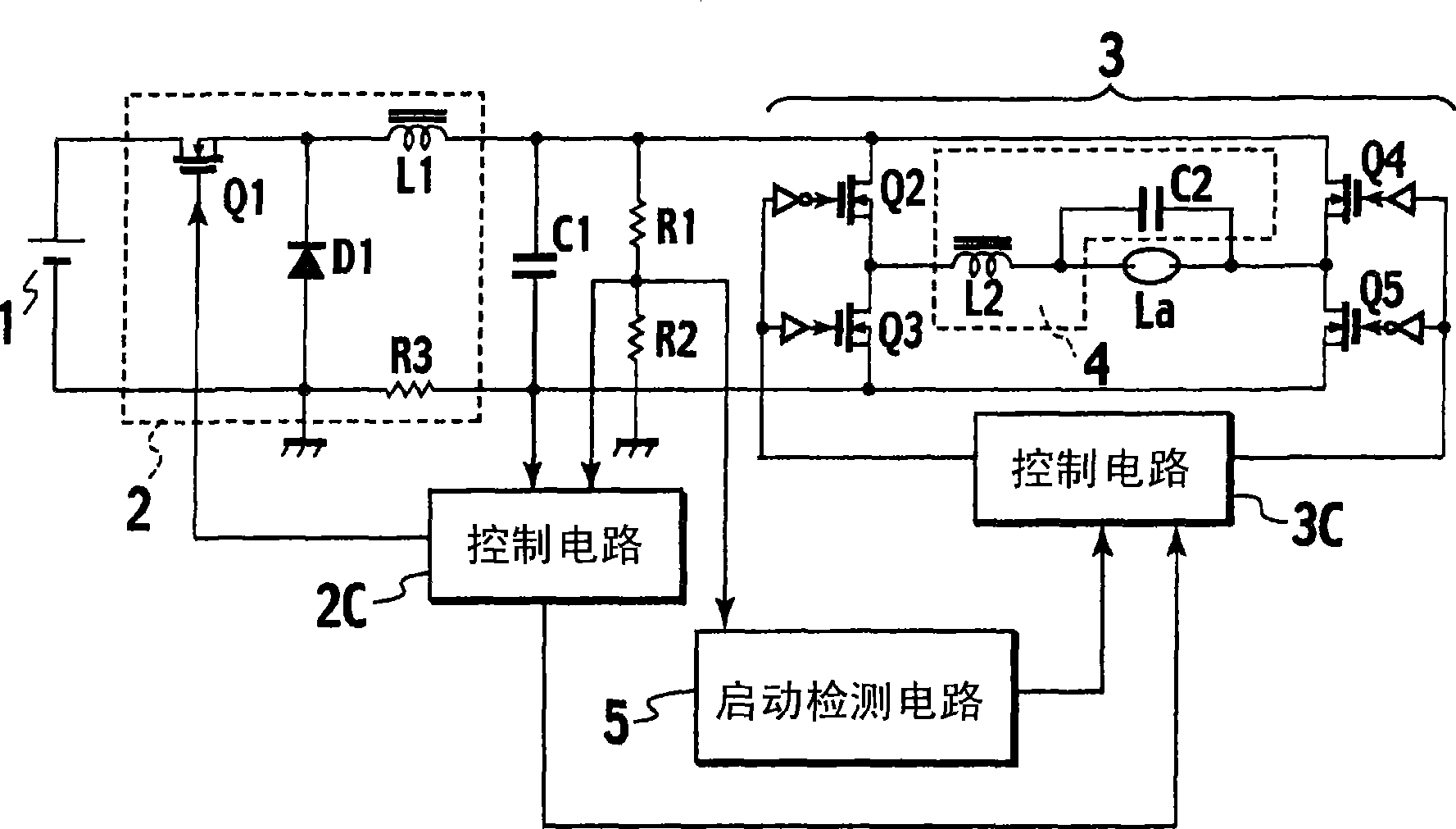
[0030] figure 1 The circuit configuration of the discharge lamp lighting device according to the first embodiment of the present invention is shown. This discharge lamp lighting device is composed of the following parts: DC power supply 1; DC / DC converter 2 for converting the power supply voltage of DC power supply 1 into a desired DC voltage; Smoothing capacitor C1; DC / AC converter 3 that converts DC voltage smoothed by smoothing capacitor C1 into AC voltage; has a resonant circuit composed of resonant capacitor C2 and resonant inductance L2 that contributes to resonant operation, and converts DC / AC The output of the inverter 3 is supplied to the starting circuit 4 for the discharge lamp La; the control circuit 2C for controlling the DC / DC converter 2 ; and the control circuit 3C for controlling the DC / AC converter 3 .

[0031] on the circuit with Image 6 The difference of the discharge lamp lighting device is that, figure 1 The shown discharge lamp lighting device inclu...

no. 2 Embodiment approach

[0066] Next, a discharge lamp lighting device according to a second embodiment of the present invention will be described. In addition, since the circuit configuration of the discharge lamp lighting device of the second embodiment is the same as that of the first embodiment, description thereof will be omitted. In addition, the same part as the above-mentioned first embodiment can be regarded as omitting the detailed description.

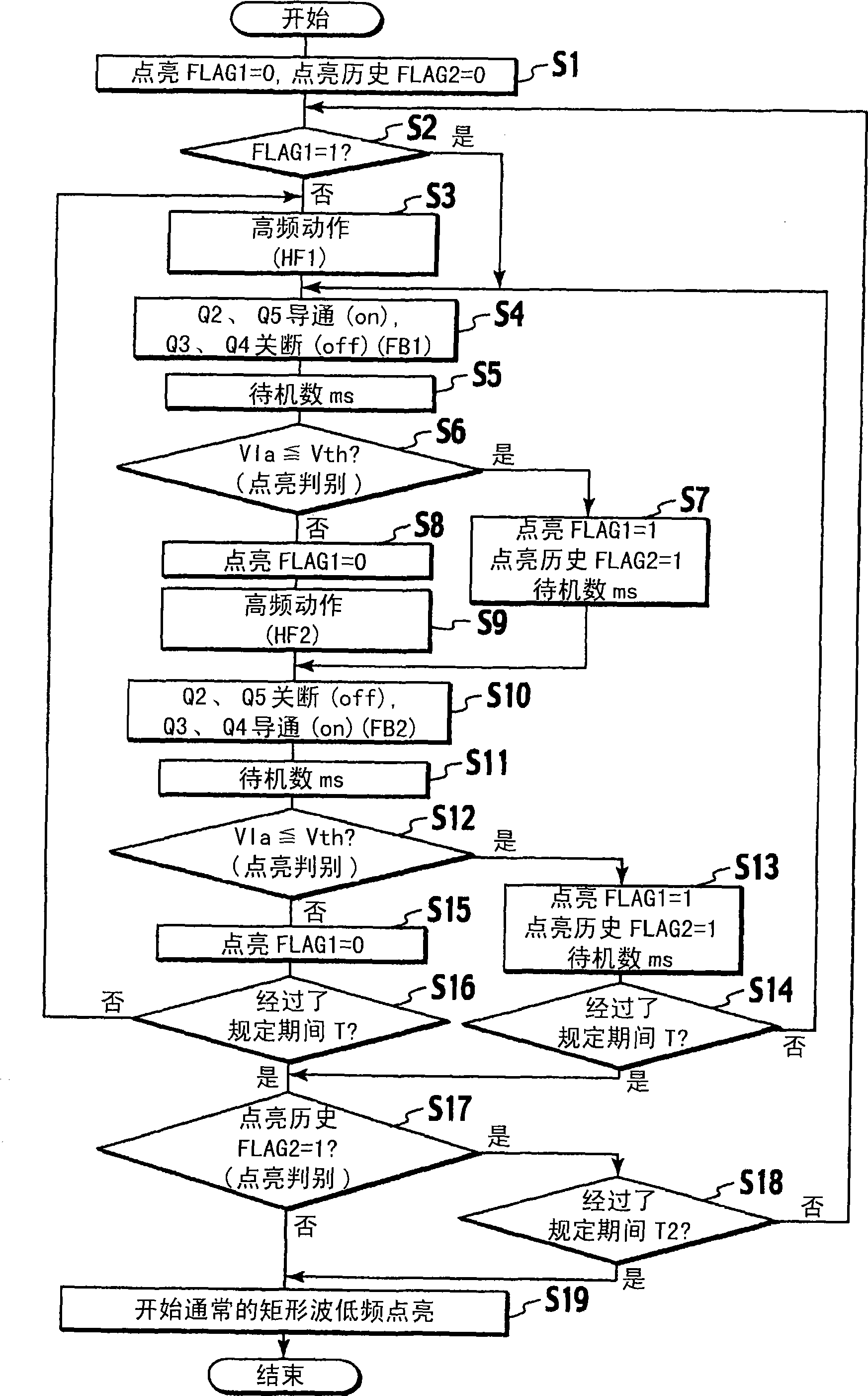
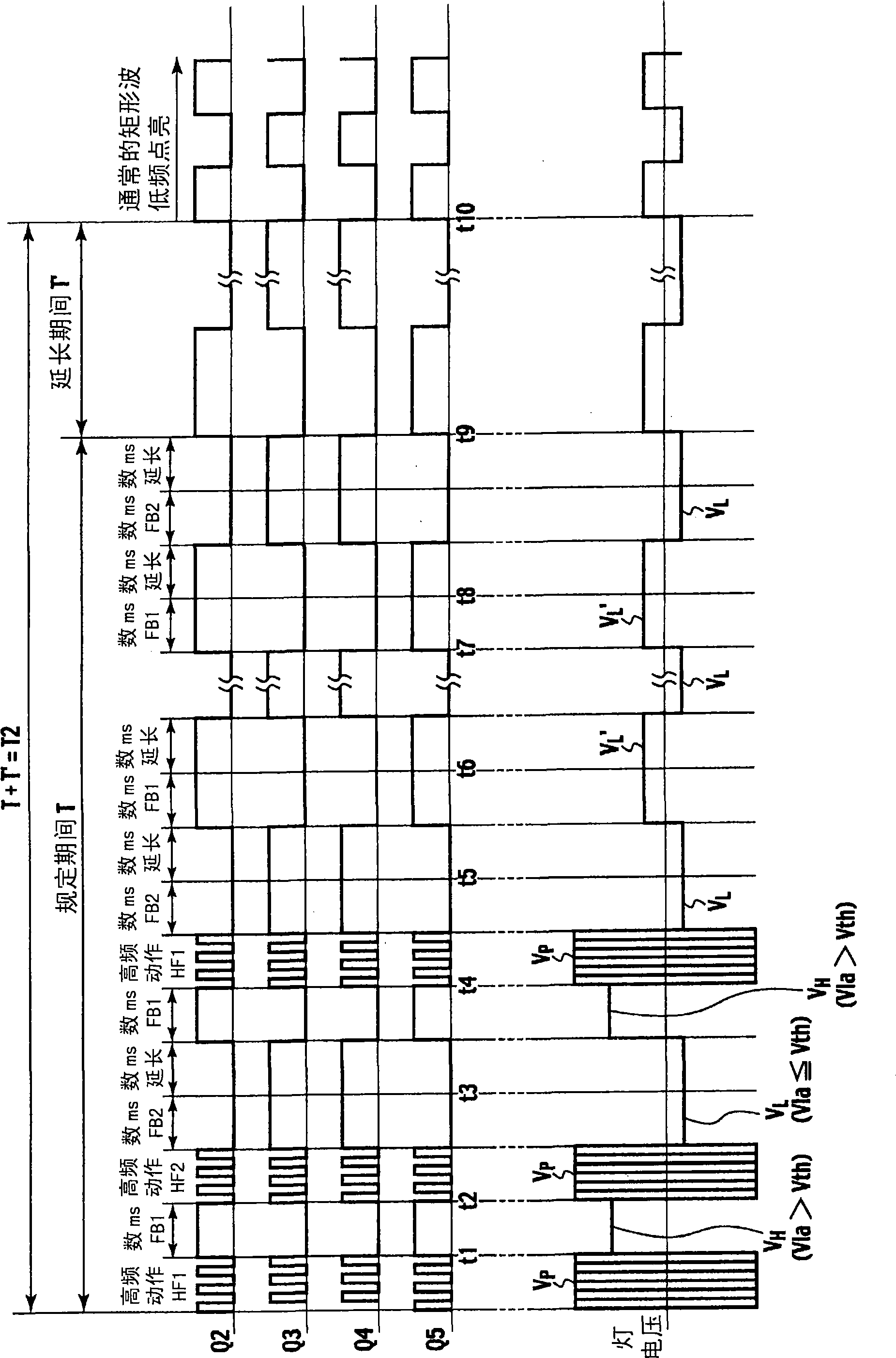
[0067] Figure 4 A control flowchart showing the operation of main parts of the second embodiment, Figure 5 The operation of the switching elements Q2 to Q5 and the waveform of the lamp voltage are shown.

[0068] Figure 4 Although the control using the lighting flag (FLAG1) and lighting history flag (FLAG2) is not shown in the figure, the figure 2 The processes of step S7, step S13, step S17, and step S18 are shown. That is, the present embodiment also extends the predetermined period T to T2 (>T) when it is determined that the discharge la...

no. 3 Embodiment approach

[0075] The discharge lamp lighting device according to any one of the first embodiment and the second embodiment can be incorporated in a lighting fixture to which the high-pressure discharge lamp La is attached, or can be used as an external ballast provided separately from the lighting fixture. In addition, such a lighting fixture may be combined with a human sensor or a brightness sensor to constitute a lighting system that controls light output based on the sensor. In addition, it can also be combined with a timer to form a lighting system that controls light output according to a time period. In addition, it can also be used in a projection-type image display device using a high-pressure discharge lamp La as a light source or in a vehicle headlamp lighting device.


PUM


Abstract

An electric discharge lamp device (La) in which periods (HF1, HF2) during which it outputs a high-frequency voltage for allowing a resonance circuit to resonate and periods (FB1, FB2) during which it outputs a rectangular wave voltage are alternately repeated when it starts up an electric discharge lamp (La) and a low-frequency rectangular wave voltage is applied to the electric discharge lamp (La) through a start-up circuit (4) when the electric discharge lamp (La) is operated. The electric discharge lamp (La) comprises a start-up detecting circuit (5) for detecting start-up of the electric discharge lamp (La) for the periods (FB1, FB2) during which the rectangular wave voltage is outputted and a control circuit (3C) for stopping the high-frequency voltage or lowering the frequency of the high-frequency voltage when the start-up of the electric discharge lamp (La) is detected. The control circuit (3C) increases the number of repetitions of the periods during which the high-frequency voltage and the rectangular wave voltage are alternately outputted when the start-up of the electric discharge lamp (La) is detected when once. With this, reliable start-up capability of an electric discharge lamp device alternately generating a high-frequency voltage and a rectangular wave voltage at start-up is ensured.

Description

technical field [0001] The present invention relates to a discharge lamp lighting device for lighting a high-pressure discharge lamp and a lighting fixture using the same. Background technique [0002] The high-pressure discharge lamp can obtain a high-brightness output beam in a compact shape, and since it is close to a point light source, it is easy to control the light distribution, so it has recently been used as an alternative to incandescent lamps or halogen lamps. It is generally believed that the voltage required to start a high-pressure discharge lamp requires a high-voltage pulse of several thousand volts. As a conventional example, the high pressure discharge lamp is as Image 6 A representative circuit configuration is shown. [0003] 1 is a DC power supply, 2 is a DC / DC converter, and 3 is a DC / AC converter. Inductor L2 and capacitor C2 form a resonant circuit. In addition, 2C is a control circuit of the DC / DC converter 2 , and 3C is a control circuit of the ...

Claims


Application Information

Patent Timeline
Patent Type & Authority Applications(China)
IPC IPC(8): H05B41/24H05B41/282
CPCH05B41/2883Y02B20/204Y10S315/07Y02B20/00
Inventor 祐福晶强力健史小西淳
Owner PANASONIC CORP
Why Eureka
Try Eureka