Wheeltrack magnetic levitation universal technology

A technology of magnetic levitation and magnetic levitation trains, which is applied to tracks, roads, buildings, etc., can solve problems such as unreliable reliability, long construction time, and land consumption, and achieve the effects of ensuring driving safety, shortening construction time, and saving construction land

Inactive Publication Date: 2009-07-15
李葛亮
View PDF0 Cites 34 Cited by
  • Summary
  • Abstract
  • Description
  • Claims
  • Application Information

AI Technical Summary

Problems solved by technology

[0006] As far as the existing magnetic levitation technology is concerned, its defects mainly lie in: 1. The tracks and vehicles of magnetic levitation are not compatible with the wheel-rail transportation system, and different magnetic levitation technologies are not compatible with each other, which makes them only suitable for point-to-point It is difficult to form a complete transportation road network system
2. The turnout structure of the maglev line is huge and complex, and the reliability cannot be guaranteed
The track of the maglev train is composed of steel beams or concrete beams. The turnout can only move the entire beam. In practice, 8 hydraulic jacks are used to move the beam weighing several hundred tons with a switching force of about 50 tons. Difficult rear locking, poor reliability
However, the transportation organization must adopt a large number of turnouts, and the elevated bridge that constitutes the maglev line is about 4-5 times that of the ordinary roadbed, so the project cost is high
[0007] In the 180 years since the first wheel-rail railway appeared in 1825, most countries have continued to build wheel-rail tracks, bridges, tunnels, railway stations and other facilities, basically forming a complete ground wheel-rail transportation system. Using the current magnetic levitation technology to replace and upgrade a transportation system with the same mileage requires a large amount of land, and the required construction time will be longer, and it is extremely uneconomical in terms of economic cost

Method used


Image

  • Wheeltrack magnetic levitation universal technology
  • Wheeltrack magnetic levitation universal technology
  • Wheeltrack magnetic levitation universal technology

Examples


Embodiment 1

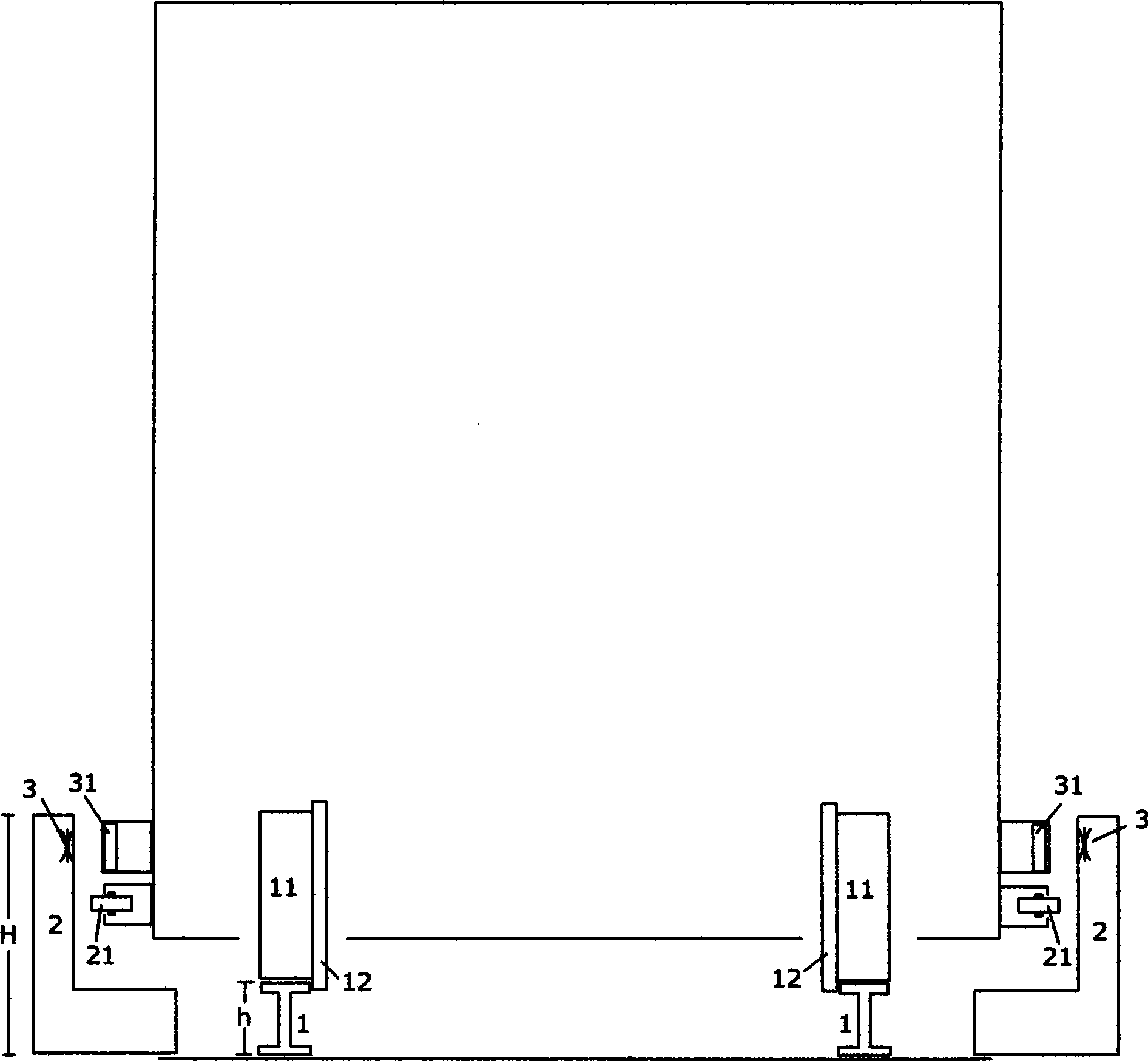
[0075] Figure 1A A cross-sectional view of a wheel-rail track with side rails and long stator windings and the corresponding wheel-rail train. Two parallel steel rails 1 are laid in the wheel-rail track, and a side rail 2 is arranged on the outside of the two steel rails 1. The inner wall of the side rail 2 is basically parallel to the steel rail 1, and the height H of the side rail 2 is greater than the height of the steel rail. h. The long stator winding 3 of the linear motor is installed and fixed on the side rail 2 and kept basically parallel to the rail 1 , and the long stator winding 3 is on the common plane of the two rails 1 .

[0076] The short rotor magnetic group 31 installed and fixed on the wheel-rail train and the long stator winding 3 installed and fixed on the side rail 2 correspond to each other and do not touch each other. The components that can be used for the short rotor magnetic group 31 include permanent magnets and normal wires. A coil electromagnet a...

Embodiment 2

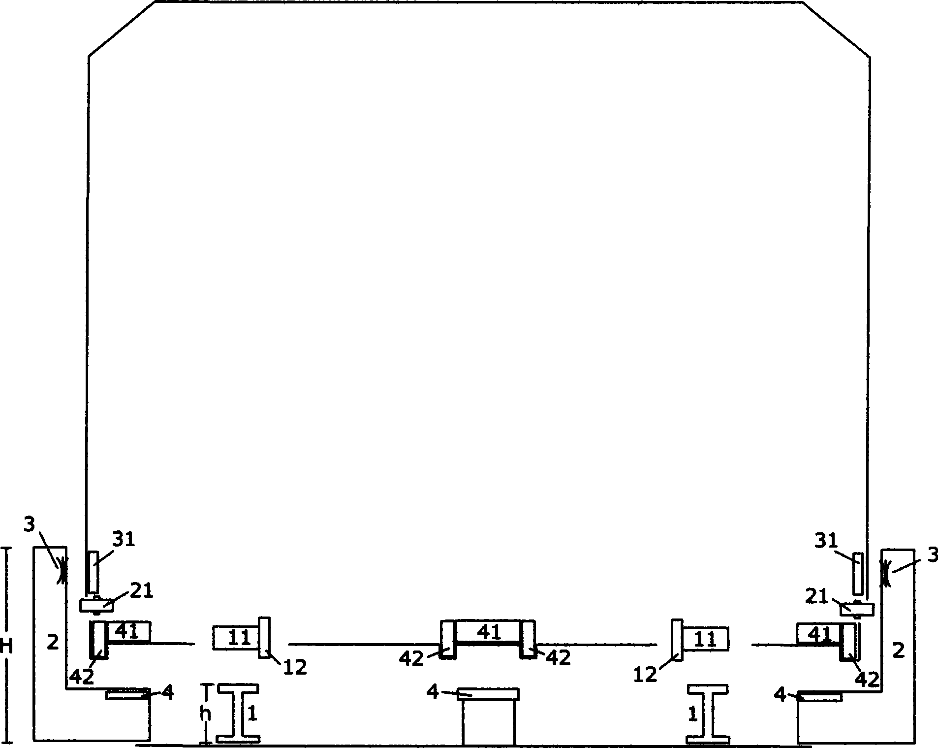
[0082] Figure 2A It is a sectional view of a wheel-rail maglev dual-purpose track and a corresponding maglev train. Two parallel steel rails 1 are laid in the wheel-rail magnetic levitation dual-purpose track shown in Figure 2, and side rails 2 are arranged on the outer sides of the two steel rails 1. The height H of 2 is greater than the height h of the rail. The long stator winding is inside the ferromagnetic track. The ferromagnetic track is made of steel, iron, nickel, cobalt or its alloy materials. The long stator winding and the ferromagnetic track together form the suspension drive track 5, and the suspension drive track 5 is located on two steel rails 1 On the common plane, the suspension drive track 5 and the steel rail 1 are basically kept parallel to each other, and the suspension drive track 5 is installed and fixed on the side rail and is located between the suspension guide drive magnetic group A 51 and the suspension guide drive magnetic group B 52 .

[0083...

Embodiment 3

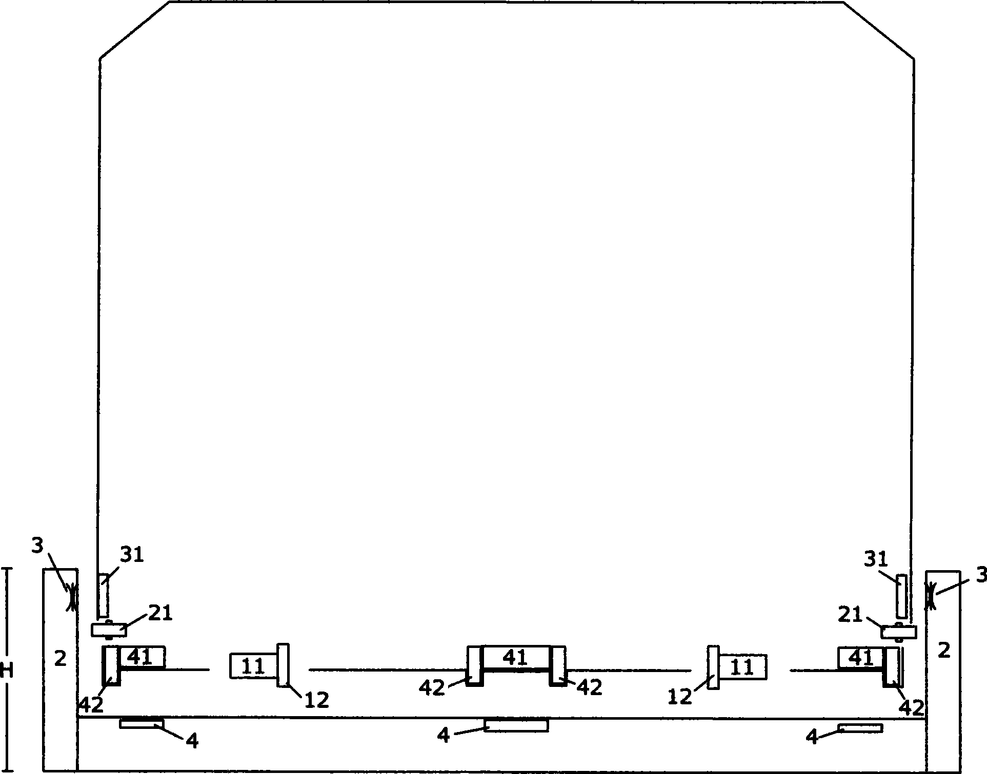
[0086] image 3 It is a sectional view of a wheel-rail maglev dual-purpose track and a corresponding maglev train. Two parallel steel rails 1 are laid in the wheel-rail track, and a side rail 2 is arranged on the outside of the two steel rails 1. The inner wall of the side rail 2 is basically parallel to the steel rail 1, and the height H of the side rail 2 is greater than the height of the steel rail. h. The long stator winding is inside the ferromagnetic track. The ferromagnetic track is made of steel, iron, nickel, cobalt or its alloy materials. The long stator winding and the ferromagnetic track together form the suspension driving track 6. The suspension driving track 6 is located on two steel rails 1 On the common plane, the suspension driving track 6 and the steel rail 1 are basically kept parallel to each other, and the suspension driving track 6 is installed and fixed on the side rail 2 . The guide track 7 installed on the side rail is basically parallel to the rail...


PUM


Abstract

The invention relates to a general technology of wheeltrack magnetic suspension, belonging to the technical field of earthbased track traffic. The general technology of wheeltrack magnetic suspension mainly comprises a wheeltrack magnetic suspension dualpurpose trackway, an electromagnetic trackway, an electromagnetic switching turnout, a suspension-oriented technology and a matched train, and is characterized in that the wheeltrack magnetic suspension dualpurpose trackway can be mutually connected with a pure suspension trackway and a common wheeltrack trackway to form a trafficable trackway communication system; the corresponding position relationship of a long stator winding and a suspension trackway which are arranged in the pure magnetic suspension trackway is consistent with the position relationship of the long stator winding and the suspension trackway which are arranged in the wheeltrack magnetic suspension dualpurpose trackway; and the track space of two steel rails in a common wheeltrack trackway is equal to the track space of two steel rails in the wheeltrack magnetic suspension dualpurpose trackway. The general technology of wheeltrack magnetic suspension combines the wheeltrack technology with the magnetic suspension technology, is used for meeting the requirement of the long-distance high-speed transportation, and has the advantages of low construction cost, high versatility, energy saving, and environmental protection, etc.

Description

technical field [0001] The field of ground rail transit technology specifically includes wheel-rail magnetic levitation dual-purpose track, electromagnetic track, electromagnetic turnout, suspension guidance technology and trains used in conjunction. Background technique [0002] The currently designed maglev transportation system is mainly divided into two directions, namely the normal conduction type adopted by Germany and the superconducting type adopted by Japan. In terms of levitation technology, it is the electromagnetic levitation system (EMS) and the electric levitation system (EDS). [0003] The Electromagnetic Suspension System (EMS) is a suction suspension system that is combined with the electromagnet on the locomotive and the ferromagnetic track on the guide rail to attract each other to generate suspension. When the normal conduction maglev train is working, first adjust the suspension of the lower part of the vehicle and the electromagnetic attraction of the ...

Claims


Application Information

Patent Timeline
Patent Type & Authority Applications(China)
IPC IPC(8): E01B25/32
Inventor 李葛亮
Owner 李葛亮
Why Eureka
Try Eureka