
Integrated direct-current charging station electrical topology and operation control method thereof

A DC charging and electrical technology, applied in parallel operation of DC power supply, DC network circuit devices, electrical components, etc., can solve the problems of complex wiring between isolation modules and charging piles, and multiplexing of isolated DC/DC modules.

Active Publication Date: 2021-05-11
JIANGSU ELECTRIC POWER RES INST +1
View PDF0 Cites 4 Cited by
  • Summary
  • Abstract
  • Description
  • Claims
  • Application Information

AI Technical Summary

Problems solved by technology

One is that the isolated DC / DC module is installed in each DC charging pile separately. This installation method saves the floor space of the DC charging station, but the isolated DC / DC module cannot be reused between charging piles, and the isolation capacity of the charging pile is fixed. ; The other is that all isolated DC / DC modules are installed together and connected to each charging pile through a transformable electrical connection. Although the capacity of isolated DC / DC can be reused between charging piles, this installation The method requires an independent station to install an isolated DC / DC module, and the wiring between the isolation module and the charging pile is complicated

Method used


Image

  • Integrated direct-current charging station electrical topology and operation control method thereof

Examples


Embodiment Construction

[0031] The technical solution of the present invention will be further described in conjunction with the accompanying drawings and embodiments.

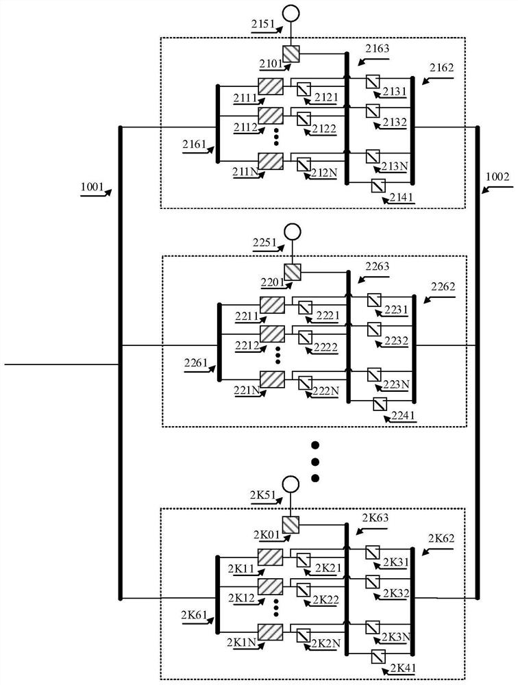
[0032] Such as figure 1 As shown, the electrical topology of the integrated DC charging station of the present invention is suitable for a high-power fast DC charging station, which includes: a power supply side DC bus 1001, a mutual aid total DC bus 1002, and K discrete charging pile units; a power supply side DC The bus bar 1001 is connected to a DC source, and the DC source includes but is not limited to a feeder line of a DC distribution network or a DC side feeder line of an AC / DC module of a charging station.

[0033] Each charging pile unit has the same configuration, and the No. 1 charging pile unit includes an input DC bus 2161, a mutual aid sub-DC bus 2162, an output DC bus 2163, and N isolated DC / DC modules ( figure 1 The middle marks are 2111~211N), N output switches ( figure 1 The middle marks are 2121~212N), N mutual ...


PUM


Abstract

The invention provides an integrated direct-current charging station electrical topology and an operation control method thereof. The integrated direct-current charging station electrical topology comprises a power supply side direct-current bus connected with a direct-current source, K discrete charging pile units and a mutual-aid total direct-current bus, each charging pile unit comprises an input direct current bus, a mutual-aid sub direct current bus, an output direct current bus, N isolation branches, a non-isolation DC / DC module and an output terminal; the input direct-current bus of each charging pile unit is connected with the power supply side direct-current bus, and the mutual-aid sub direct-current bus of each charging pile unit is connected with the mutual-aid total direct-current bus; each isolation branch has the same configuration and comprises an output branch and a mutual assistance branch; when all the output branches in the charging pile units connected with the electric vehicle are started, and the output power cannot meet the power demand of the electric vehicle, the power demand of the electric vehicle is met by starting the mutual-aid branches of other charging pile units.

Description

technical field [0001] The invention belongs to the technical field of electric vehicle charging, and in particular relates to a high-efficiency integrated DC charging station electrical topology and an operation control method thereof. Background technique [0002] The existing electric vehicle DC charging station is mainly composed of multiple DC charging piles. In order to meet the charging safety requirements, the high-frequency electrical isolation method is preferably used in the DC charging pile to isolate the DC bus on the power supply side and the DC bus on the charging side at high frequency. [0003] At present, high-frequency DC isolation is realized by installing an isolation DC / DC module between the DC bus on the power supply side and the DC bus on the charging side. There are mainly two types of electrical topologies. One is that the isolated DC / DC module is installed in each DC charging pile separately. This installation method saves the floor space of the DC...

Claims


Application Information

Patent Timeline
IPC IPC(8): H02J1/10H02M1/00
CPCH02J1/109H02M1/00Y02T90/12Y02T10/7072Y02T10/70B60L53/11B60L53/62B60L53/67B60L53/63
Inventor 袁宇波孙天奎杨景刚高磊李群刘建陈舒方鑫肖小龙庄舒仪
Owner JIANGSU ELECTRIC POWER RES INST
Learn More