Drilling method for steam assisted gravity draining oil well

An auxiliary gravity and oil drainage technology, which is applied in the direction of wellbore/well components, earthwork drilling, production fluid, etc., can solve the problems of prone to steam channeling, plugging of production wells, affecting recovery rate, etc., and achieve the goal of reducing relative errors Effect

Inactive Publication Date: 2009-07-15
兴和鹏能源技术(北京)股份有限公司
View PDF0 Cites 18 Cited by
  • Summary
  • Abstract
  • Description
  • Claims
  • Application Information

AI Technical Summary

Problems solved by technology

If the distance between the two wells is too close, steam channeling is prone to occur, and steam water cones will be formed after the steam condenses, blocking the production well 2; and if the two wells are far apart due to too large a distance error or direction deviation, the heating effect will be reduced. Affected, affecting recovery
[0005] However, in the current existing SAGD oil well drilling methods, the two wells are usually drilled independently according to the pre-completed design drawings, although in the process of drilling each well, frequent measurement, frequent calculation, frequent analysis and However, the drilling reference point of the two wells is still the well itself. Although the absolute error of the two wells will be reduced

Method used


Image

  • Drilling method for steam assisted gravity draining oil well
  • Drilling method for steam assisted gravity draining oil well
  • Drilling method for steam assisted gravity draining oil well

Examples


Embodiment approach 1

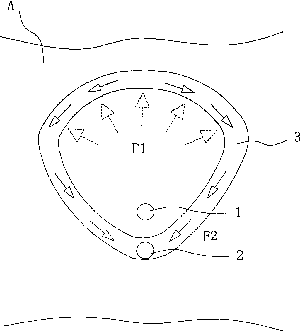
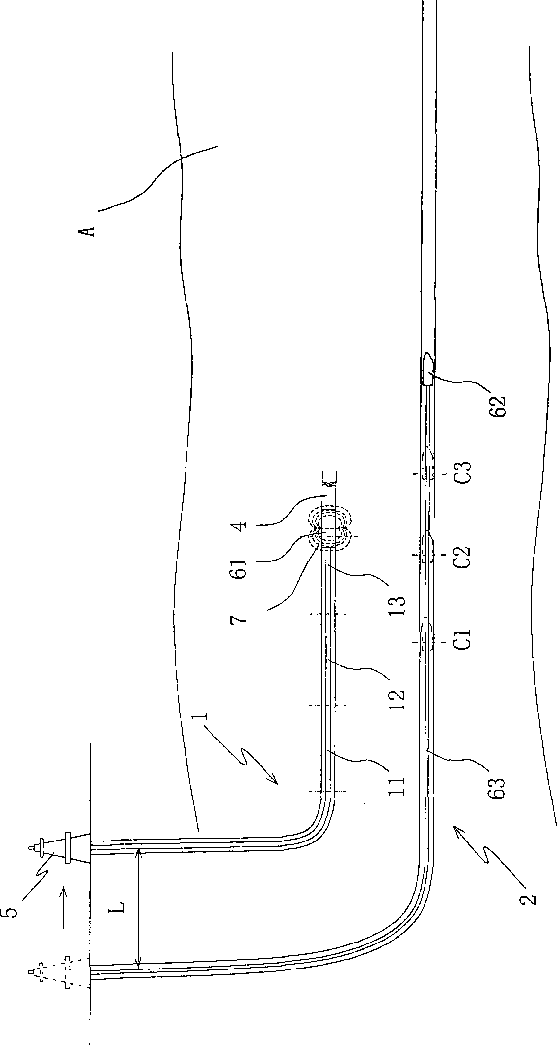
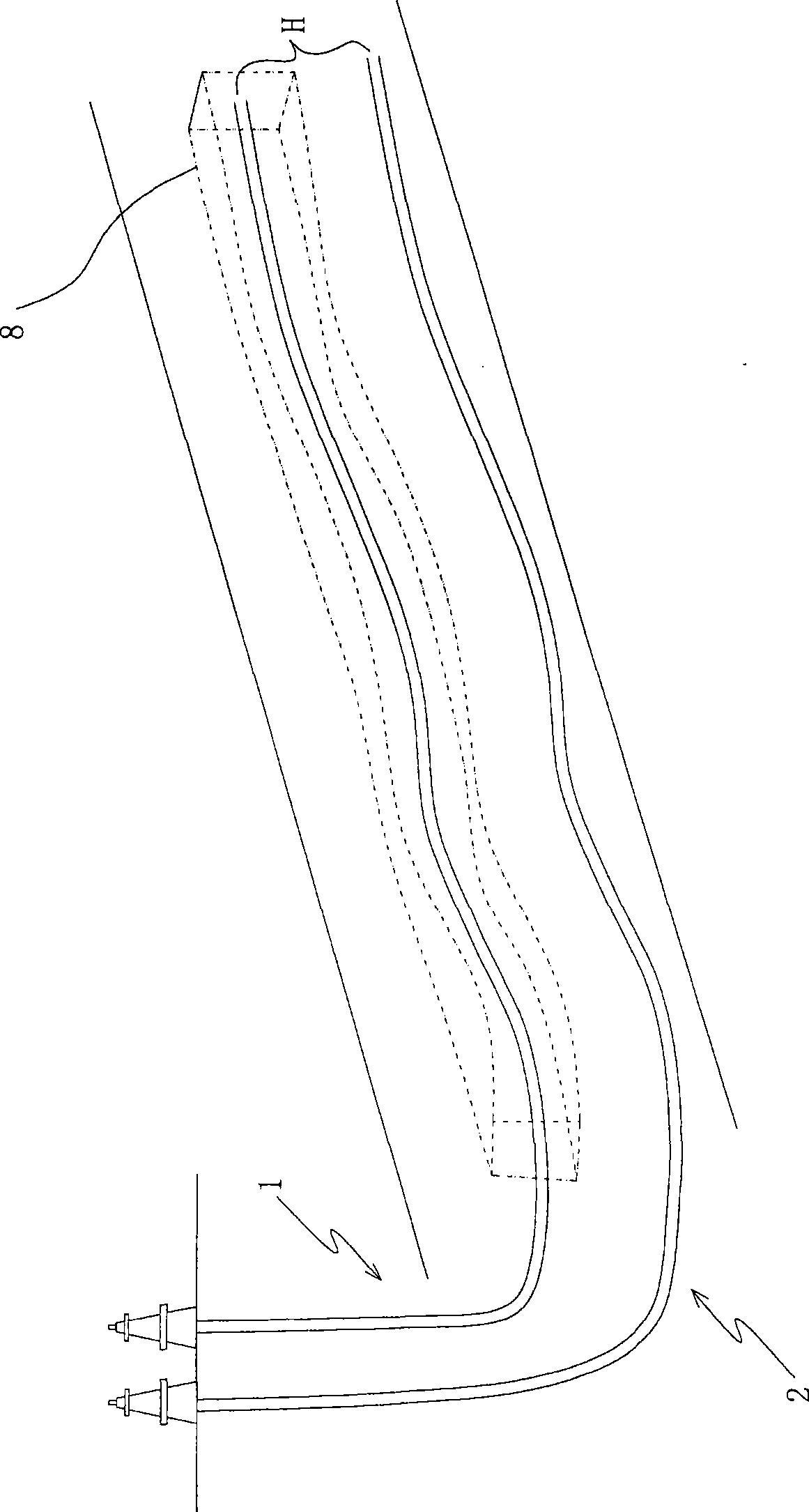
[0017] Such as figure 2 As shown, the present invention provides a drilling method for steam-assisted gravity drainage oil wells, which are used to drill two parallel horizontal wells at the bottom of the reservoir A, the upper horizontal well is the gas injection well 1, and the lower horizontal well is the gas injection well 1. The flat well is the production well 2, and the specific steps include:

[0018] 1. First drill the production well 2 below. Drilling single well technology is relatively mature. Drilling tools with measurement-while-drilling systems can be used in conventional methods to easily ensure that the absolute error of production wells is within the allowable range. The specific operation process is: Drill a certain length of vertical well section, Afterwards, build-up drilling, drill a 20-meter or so inclined vertical well section at an inclination angle of about 55 degrees, which is convenient for lowering the oil production pump, and then continue to bu...

Embodiment approach 2

[0028] The specific steps, principles and effects of this embodiment are basically the same as those of Embodiment 1, except that the drilling sequence of the two wells has changed. In this embodiment, the steam injection well is drilled first, and then the production well is drilled Well, other contents will not be described in detail.


PUM


Abstract

The invention discloses a well-drilling method for steam-aided gravity draining oil well used for drilling an upper well and a lower well which are horizontally parallel; the horizontal well at the upper part is a gas-injection well, and the horizontal well at the lower part is a producing well; the method is characterized in that: one of the two horizontal wells is drilled, and the other is drilled according to drill hole trajectory of the finished horizontal well. Joint measurement control is carried out by utilizing a magnetic-conducting measurement system and a measurement while drilling system, and then the horizontal well section of the second horizontal well, which is parallel to the horizontal well section of the finished horizontal well, is drilled by the guidance of real-time data of the drilling trajectory of the finished horizontal well section, thus forming a magnetic-conducting loop-closed measurement drilling mode which is correspondingly sealed between the finished well and the well to be drilled, leading the error of the drill hole trajectory of the two wells to be synchronous and effectively controlling the relative deviation of the two horizontal well sections; therefore, SAGD oil wells which is in accordance with ideal error requirements are successfully drilled, thereby greatly improving recovery efficiency of thick oil pool.

Description

technical field [0001] The invention relates to a drilling method for heavy oil reservoirs, in particular to a drilling method for steam-assisted gravity drainage oil wells. Background technique [0002] Viscous oil, extra heavy oil and heavy oil reservoirs are extremely high, difficult to exploit and low recovery. The recovery rate of ordinary vertical wells is less than 10%, and that of horizontal wells is less than 20%. At present, the steam assisted gravity drainage (SAGD) production method has appeared, which has greatly improved the recovery rate of heavy oil, extra heavy oil and heavy oil reservoirs. [0003] Such as figure 1 As shown, the production principle of SAGD oil well is: drill a pair of parallel horizontal wells above and below near the bottom of reservoir A. The lower horizontal well is the production well 2. When exploiting high-viscosity oil, usually all two horizontal wells are injected with high-temperature steam to form a circulating heating zone t...

Claims


Application Information

Patent Timeline
IPC IPC(8): E21B43/00E21B43/24
Inventor 张和茂胡鹏李忠君丁畅
Owner 兴和鹏能源技术(北京)股份有限公司
Why Eureka
Try Eureka