Oil pump of flushing well

A technology of well pump and pump barrel, applied in the field of well-flushing oil pump, can solve the problems of reducing pump efficiency air lock, shortening the effective stroke, damage, etc., and achieving the effect of increasing the filling factor, increasing the effective stroke, and reducing fatigue loss

Inactive Publication Date: 2009-07-15
韩东明
View PDF5 Cites 5 Cited by
  • Summary
  • Abstract
  • Description
  • Claims
  • Application Information

AI Technical Summary

Problems solved by technology

In mechanical oil production wells, when the sand or wax content is serious, accidents such as hard or soft jams often occur and may cause damage to equipment, etc., and the existing pump cannot send the sand back to the pump
In addition, due to the gas contained in the oil flow, the effective stroke of the pump is shortened, the pump efficiency is reduced and even air lock occurs, which has a great impact on oil production

Method used


Image

  • Oil pump of flushing well
  • Oil pump of flushing well

Examples


Embodiment Construction

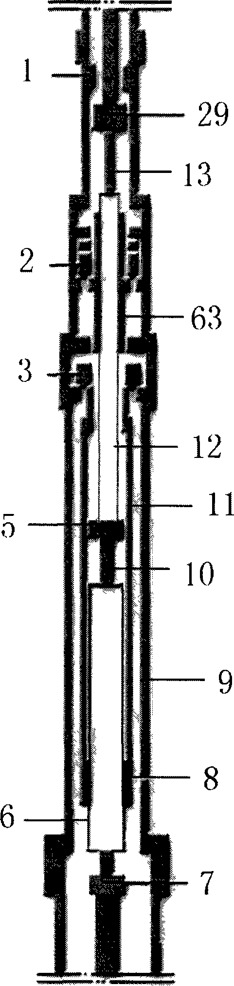
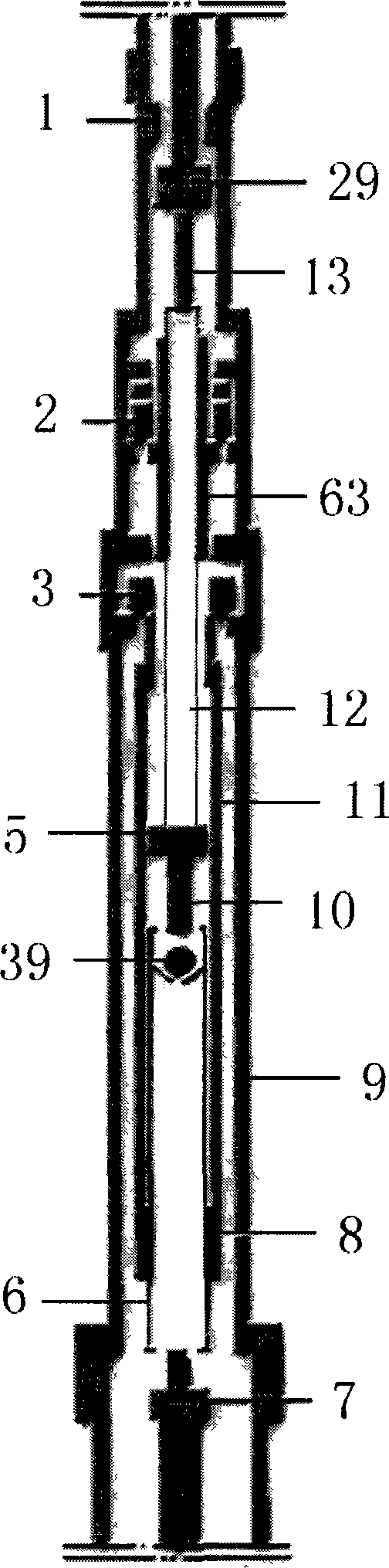
[0009] exist figure 1 Among them, release joint 1, oil outlet valve 2, upper pump barrel 63, oil inlet valve 3, outer pump tube 9, inner pump tube 11, and lower pump barrel 8 are sequentially connected to form the inlet and outlet channels of the pump; 29. The upper reducing rod 13, the upper plunger 12, the limit joint 5, the lower reducing rod 10, the lower plunger 6, and the weighting rod 7 are sequentially connected to form the suction mechanism of the pump. The length of the upper plunger 12 is greater than the stroke length of the pump relative to the length of the upper pump barrel 63 and the length of the lower plunger 6 relative to the lower pump barrel 8 . During the upstroke, the suction mechanism moves upwards, increasing the pressure in the annular space between the inner pump barrel 11 and the upper plunger 12, forcing the oil inlet valve 3 to close, and the oil outlet valve 2 to open, and the liquid in the pump is discharged to the ground; During the downstroke...


PUM


Abstract

The invention relates to an oil-well pump capable of direct flushing. The oil-well pump is underground equipment which has the effects of sand prevention, gas prevention, wax prevention and high pump efficiency and is applied to oil exploration industry. In the oil-well pump, an upper plunger piston and a lower plunger piston are equipped with sand prevention slots, can send the sands deposited in the sand prevention slots to the underside of the pump to realize sand prevention. When the plunger pistons fall to a pump-bumping position, oil pipes above and below the pump are in communicated state by a pump cavity, thereby realizing the function of direct flushing. In the oil-well pump, an oil inlet valve can be opened easily under the hydraulic feedback action, thereby increasing the fullness coefficient, reducing the bend of a sucker rod, increasing the effective stroke of the pump, preventing air lock, reducing the fatigue loss of the sucker rod, and the oil-well pump has the functions and the characteristics of gas prevention and high pump efficiency.

Description

technical field [0001] The invention relates to an oil pump capable of flushing wells, in particular to an underground deep well pump which is widely used in the oil exploitation industry and has the functions of sand prevention, gas prevention, wax prevention, high pump efficiency and oil drainage. technical background [0002] In the reservoir oil layer, generally contain sand, gas, wax or glue and so on. In mechanical oil production wells, accidents such as hard jams or soft jams often occur when the sand or wax content is serious, which may cause damage to equipment, etc., and the existing pumps cannot send the sand back to the pump. In addition, due to the gas contained in the oil flow, the effective stroke of the pump is shortened, the pump efficiency is reduced and even an air lock occurs, which has a great impact on oil production. Contents of the invention [0003] In order to solve the impact of sand, gas, wax or gum in the oil layer on oil production, the inven...

Claims


Application Information

Patent Timeline
Patent Type & Authority Applications(China)
IPC IPC(8): F04B47/12F04B53/14F04B53/10F04B53/12E21B43/00
Inventor 韩东明
Owner 韩东明
Why Eureka
Try Eureka