Waste heat recovery and utilization system for waste gas of revolving furnace

A waste heat recovery and flue gas purification system technology, applied in the field of energy saving and emission reduction

Inactive Publication Date: 2009-07-15
徐文玉
View PDF1 Cites 6 Cited by
  • Summary
  • Abstract
  • Description
  • Claims
  • Application Information

AI Technical Summary

Problems solved by technology

The problem to be solved in this patent application is how to use the saturated steam of the waste heat boiler in the iron and steel plant to generate electricity, but it does not involve how to recover more waste hea

Method used


Image

  • Waste heat recovery and utilization system for waste gas of revolving furnace
  • Waste heat recovery and utilization system for waste gas of revolving furnace
  • Waste heat recovery and utilization system for waste gas of revolving furnace

Examples


Embodiment Construction

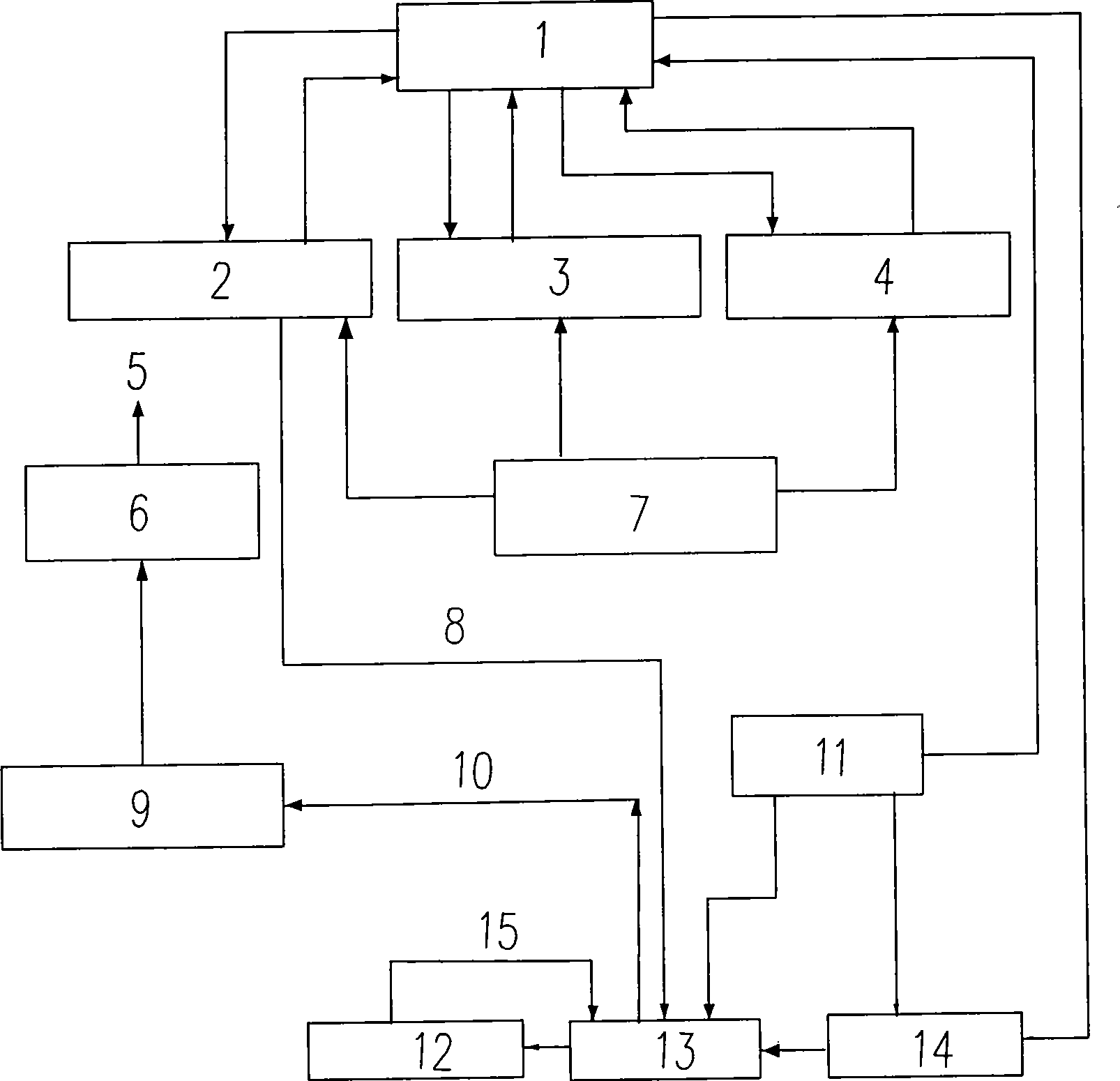
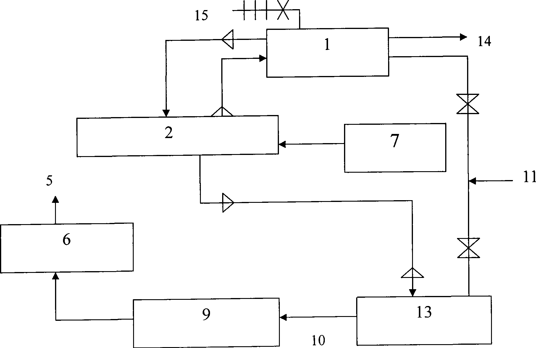
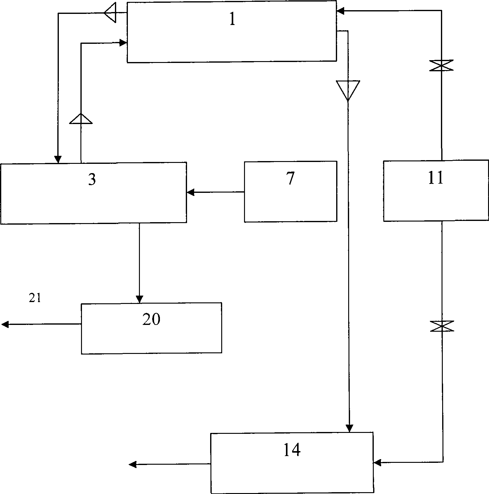
[0034] The specific implementation manner of the present invention will be further described below in conjunction with the accompanying drawings.

[0035] Such as figure 1 , 2 As shown, the converter exhaust gas waste heat recovery and utilization system of the present invention includes a converter flue primary waste heat boiler 2, a steam-water separator 1, a coaming and a ceiling 4, a flue gas purification system 6, a secondary dust removal smoke box 3, and a secondary dust collector . Turbine generator 12. Electric automation control system, characterized in that a converter waste gas descending pipeline 8 is connected to the flue gas outlet of the primary waste heat boiler 2 in the converter flue, and the converter waste gas descending pipeline 8 is connected to the secondary The vaporization and cooling system of the waste heat boiler is connected, and the vaporization and cooling system of the secondary waste heat boiler consists of a secondary waste heat boiler 13, a ...


PUM


Abstract

The invention relates to a converter exhaust gas heat recycling system, comprises a converter smoke helmet first exhaust-heat boiler, a steam-water separator, a coaming plate and ceiling, a smoke purifying system, a second dust smoke removing box, a smoke purifying system and a steam generator; the smoke outlet of the converter smoke helmet calandria exhaust-heat boiler is connected with a converter waste gas down going pipeline which is connected with a second exhaust-heat boiler system; the second exhaust-heat boiler system consists of a second exhaust-heat boiler, a steam outlet, a smoke outlet, a soft water pipeline, a flowmeter and pipeline valve gate, a steam pressure meter, a fluviograph and safety valve and a suction adjusting multi-leaf valve. The invention collects all the steam from the first dedusting, second dedusting, second recovery and upper coaming plate of the exhaust-heat boiler, recycles the converter waste gas heat as much as possible, reduces the water consumption of OG system, reduces the cement slurry treating capacity in the subsequent processes, achieves the aim of energy saving and emission reducing, and realizes the converter steelmaking with minus energy consumption.

Description

technical field [0001] The invention relates to the technical field of energy saving and emission reduction in the converter steelmaking process, in particular to a converter waste gas waste heat recovery and utilization system. Background technique [0002] During the blowing process of converter steelmaking, a large amount of high-temperature waste gas with a temperature as high as 1600°C-1700°C will be produced. The high-temperature waste gas is discharged from the converter mouth, through the movable hood and flue (pipe-type waste heat boiler), and the steam generated by the waste heat boiler is sent to the steam-water separator, and the temperature of the waste gas is reduced from 1600°C-1700°C to 900°C-1000°C , and then enter the OG system for wet dust removal, use a large amount of cooling water to cool the exhaust gas, the water and the furnace dust in the exhaust gas form a large amount of dust slurry, and then dehydrate the dust slurry. [0003] At present, most c...

Claims


Application Information

Patent Timeline
IPC IPC(8): F27D17/00F01K11/02F01K27/02
CPCY02P10/25Y02P40/121Y02P80/15
Inventor 徐文玉黄楠黄轩昊
Owner 徐文玉
Why Eureka
Try Eureka