
Calibration method for image measuring system

A calibration method and image measurement technology, applied in the direction of camera devices, etc., can solve the problems of not being able to accurately calibrate the relationship between the observed object and the image, not obtaining the physical coordinates of the calibration point, etc., to meet the real-time requirements, small footprint, high The effect of precision calibration

Active Publication Date: 2009-07-15
BAOSHAN IRON & STEEL CO LTD
View PDF3 Cites 10 Cited by
  • Summary
  • Abstract
  • Description
  • Claims
  • Application Information

AI Technical Summary

Problems solved by technology

The calibrator is only used for position indication and does not obtain the physical coordinates of the calibration point, so it cannot be used to accurately calibrate the relationship between the observed object and the image

Method used


Image

  • Calibration method for image measuring system
  • Calibration method for image measuring system
  • Calibration method for image measuring system

Examples


Embodiment Construction

[0039] The technical solutions of the present invention will be further described below in conjunction with the accompanying drawings and embodiments.

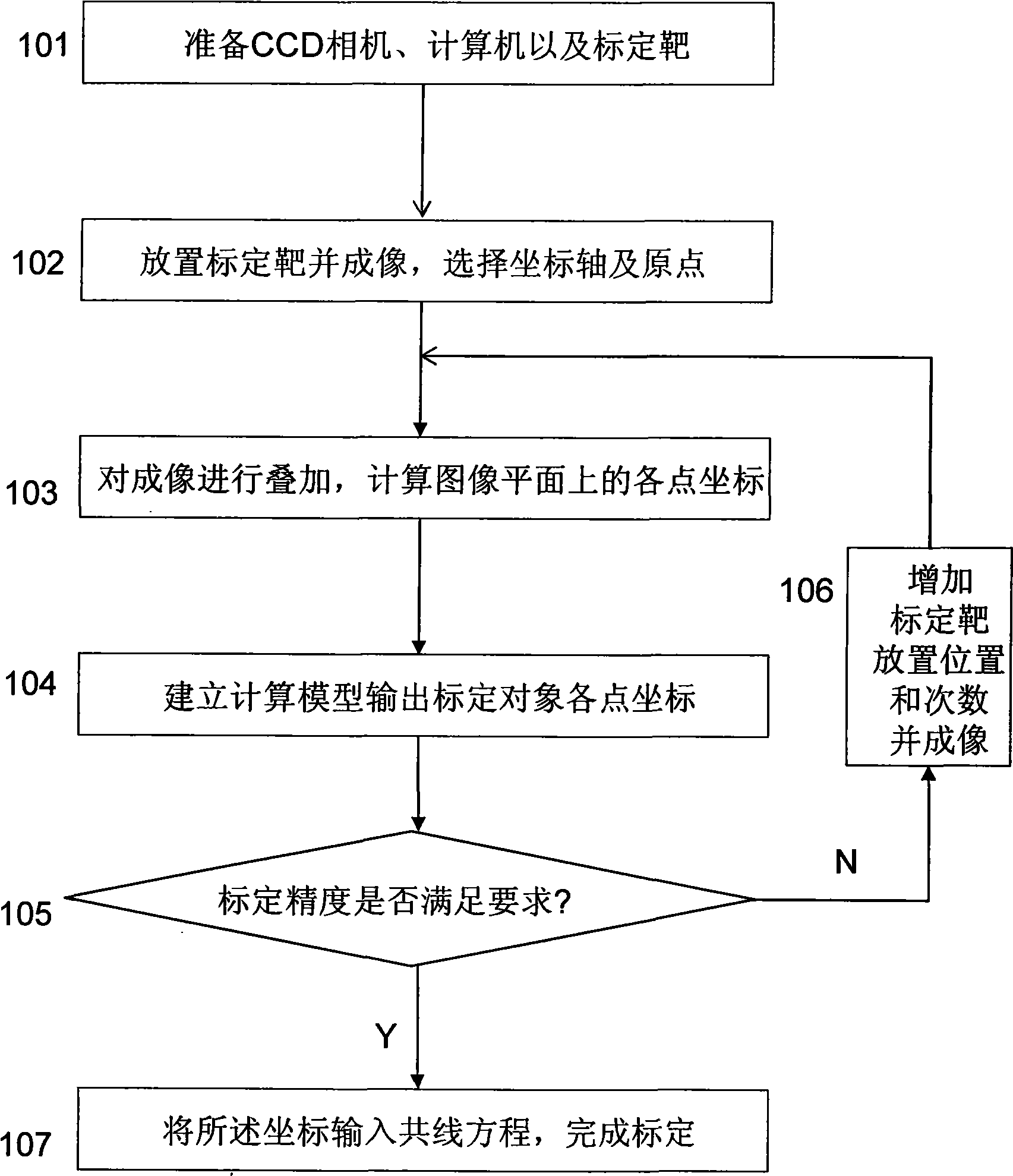
[0040] refer to figure 1 , a method for calibrating an image measurement system according to the present invention, comprising the following steps:

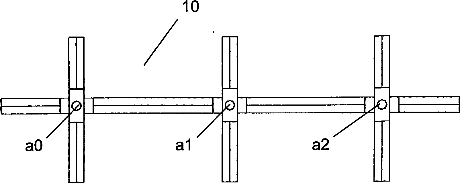
[0041] 101. Prepare the CCD camera 20, the computer 30 and the calibration target 10. The computer 30 is connected with the CCD camera 20, the calibration target 10 has calibration points a0, a1, a2, and the calibration points a0, a1, a2 are on the same horizontal line and keep a fixed distance between them, refer to figure 2 and Figure 5 .

[0042] The calibration target 10 includes a body 11 and three rotatable feet 12, the rotatable feet 12 are installed on the centerline of the body 11 through a reference axis, and the center points a0, a1, a2 of the three reference axes on the centerline as the calibration point, refer to figure 2 .

[0043]The bottom surface of the...


PUM


Abstract

The invention relates to a scaling method in image measuring system, which comprises: placing simple scaling targets on the scaled plane in order, superposing and imaging; calculating out the coordinate of every point on the image plane; calculating out the coordinate of every scaled point on the scaled plane by using the geometric constant principle between the scaled plane and the image plane; and inputting the coordinates into the conllinear equation of the scaled plane and the image plane to obtain the relation between the scaled plane and the image plane. The invention is especially suitable for industrialized large visual field image measuring system, can meet the real-time requirement of production site, can increase the scaling target placing time according to the scaling precision requirement to realize high precision scaling, avoids the constraint scaling by plane fixing mechanical devices in the existing technologies, and achieves the advantages of fast, simple, efficient, reliable, small scaling target occupation area, easy keeping and high precision.

Description

technical field [0001] The invention relates to the technical field of image measurement systems in automatic instruments, and more specifically, relates to a calibration method for image measurement systems. Background technique [0002] Calibration technology is the guarantee of the reliability and accuracy of the measurement system, and the image measurement system is no exception. The optical lens system cannot realize the ideal linear pinhole model, and the camera will bring some distortion of the corresponding relationship when shooting. The imaging process of the camera is a Degenerate projective transformation from 3D space to 2D space, in which there is the principle of projective invariant geometric relationship, using this principle to calibrate the camera system, and correct the distortion during calibration; at the same time, the relationship between the camera and the measured object The spatial mapping relationship among them is determined in the calibration t...

Claims


Application Information

Patent Timeline
Patent Type & Authority Applications(China)
IPC IPC(8): G01C11/02
Inventor 夏勇方志宏
Owner BAOSHAN IRON & STEEL CO LTD
Learn More