Arrangement comprising a shunt resistor and method for producing the same

A shunt resistor and resistance zone technology, applied in resistor cooling/heating/ventilation devices, resistors, circuit devices, etc., can solve the problems of decreased soldering function, high temperature of shunt resistors, and delamination of shunt resistors

Active Publication Date: 2009-07-15
INFINEON TECH AG
View PDF0 Cites 10 Cited by
  • Summary
  • Abstract
  • Description
  • Claims
  • Application Information

AI Technical Summary

Problems solved by technology

Since the two properties do not combine well, the shunt resistors are often very hot, and as

Method used


Image

  • Arrangement comprising a shunt resistor and method for producing the same
  • Arrangement comprising a shunt resistor and method for producing the same
  • Arrangement comprising a shunt resistor and method for producing the same

Examples


Embodiment Construction

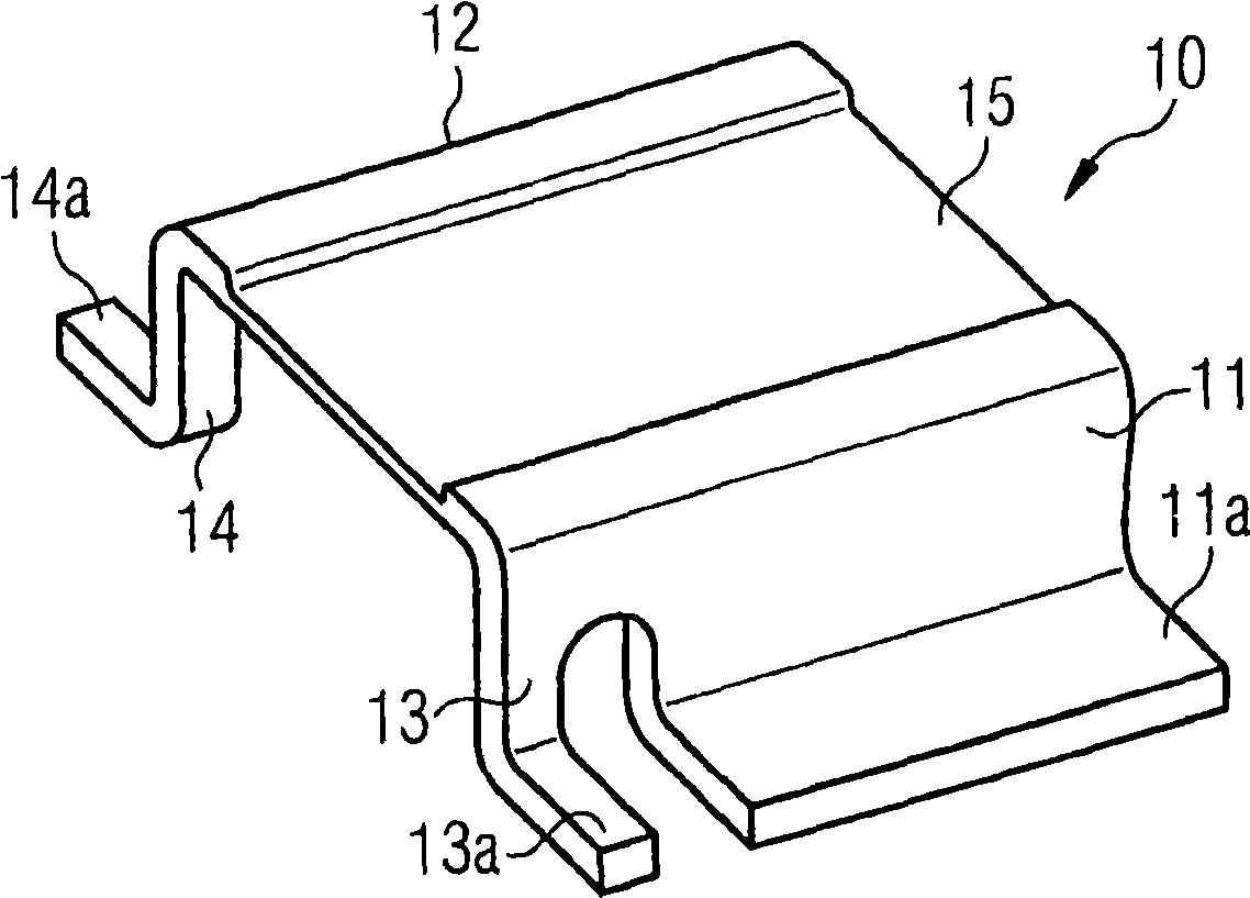
[0026] figure 1 is a perspective view of an example of a shunt resistor 10 . The shunt resistor 10 includes a first connection pin 11 , a second connection pin 12 , an optional third connection pin 13 and an optional fourth connection pin 14 . Each of the terminal pins 11, 12, 13, 14 includes a flange 11a, 12a (hidden in the figure 1 Middle), 13a and 14a. Between the first connection pin 11 and the second connection pin 12 and between the third connection pin 13 and the fourth connection pin 14 is arranged a resistance zone 15 with a predetermined resistance value. Compared with the resistance area 15, the first connecting pin 11 and the second connecting pin 12 have a low resistance value. For the resistance region, for example, a metal alloy having a low relationship between heat and resistivity can be used. Examples of alloys already available in the market are, (comprising, for example, about 82% to 84% by weight of copper, 12% to 15% by weight of manganese and 2% to...


PUM


Abstract

The invention relates to an arrangement comprising a shunt resistor with at least an electrically conductive first connecting leg and an electrically conductive second connecting leg. A resistance area of the shunt resistor is electrically connected to the first connecting leg and to the second connecting leg. The arrangement further comprises a circuit carrier with a first metallization and a second metallization. The first connecting leg is directly joined to the first metallization and the second connecting leg is directly joined to the second metallization. The resistance area of the shunt resistor is in thermal contact with the thermally conductive substrate by use of a thermal filler arranged between the resistance area and the substrate, and/or by directly contacting the resistance area with the substrate. The invention further relates to a method for producing an arrangement with a shunt resistor and a circuit carrier.

Description

technical field [0001] The invention relates to a device comprising a shunt resistor. Background technique [0002] Shunt resistors are used, for example, for the precise determination of current flow in power semiconductor modules. Conventional shunt resistors are used in a wide range of applications and are electrically connected to circuit carriers, for example by soldering. Physically, it is required that the two properties are incompatible. The first characteristic is that the resistance value is rather large so that the current can be measured accurately. The second characteristic is low thermal resistance to avoid overheating due to dissipated power. Since the two properties do not combine well, shunt resistors are often very hot, and as a result, degradation of the solder function and delamination of the shunt resistor may occur. This is one of the reasons why shunt resistors are generally specified at a certain maximum temperature - eg 250°C. Contents of the i...

Claims


Application Information

Patent Timeline
IPC IPC(8): H01C13/00
CPCH05K2203/0195H05K2201/10022H05K2201/10757H05K1/0268H05K2201/10651H05K1/0203H05K2203/049H05K2201/0209G01R1/203H01C1/014H05K2203/0285H05K1/0263H05K3/328H01C1/08H01C1/14H01L2924/19107
Inventor M·舒尔茨P·坎沙特
Owner INFINEON TECH AG
Why Eureka
Try Eureka