Motor for dust collector

A technology for vacuum cleaners and casings, which is applied in the fields of vacuum cleaner motors and heat dissipation structures, can solve the problems of complex structure and poor heat dissipation effect, and achieves the effects of good cooling effect, small gap and improved heat dissipation effect.

Active Publication Date: 2009-07-15
CINDERSON TECH (SUZHOU) CO LTD
View PDF0 Cites 14 Cited by
  • Summary
  • Abstract
  • Description
  • Claims
  • Application Information

AI Technical Summary

Problems solved by technology

[0004] The purpose of the present invention is to overcome the deficiencies of the prior art, and provide a wet and dry vacuum cleaner motor, which aims to effectively solve the existing problems of t

Method used


Image

  • Motor for dust collector
  • Motor for dust collector

Examples


Example Embodiment

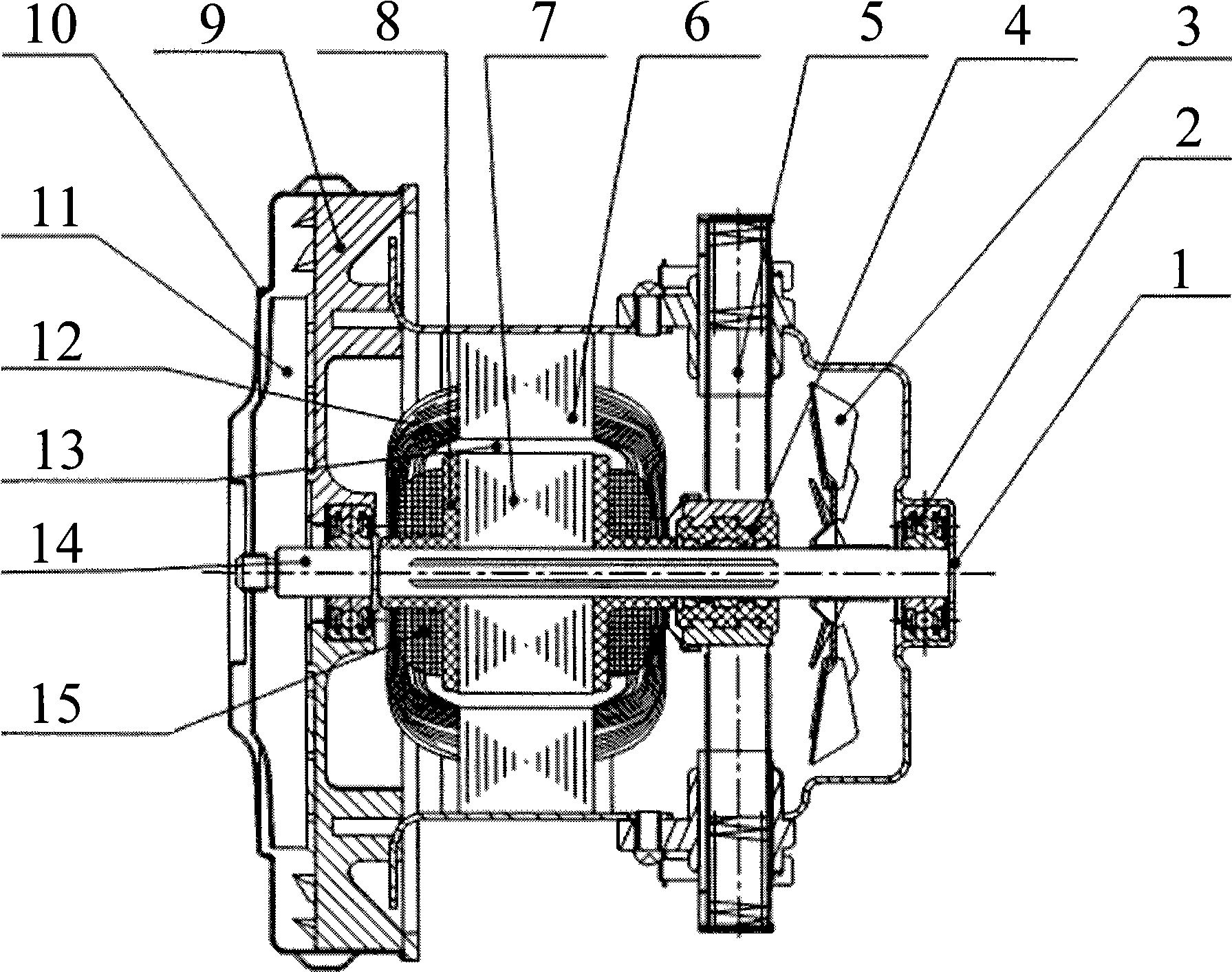
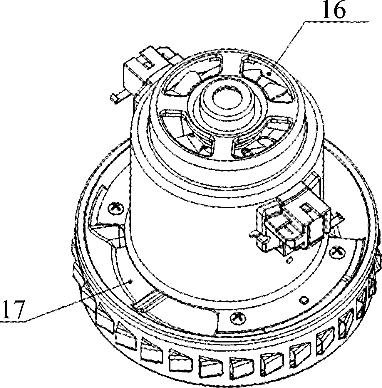
[0019] Such as figure 1 As shown, the wet and dry vacuum cleaner motor includes a stator iron core 6, a rotor iron core 7, a fixed impeller 9, a wind cover 10, a movable impeller 11, a stator winding 12, a rotor winding 15 and an insulating end plate 8. A stator and rotor air gap 13 is formed between 6 and the rotor core 7. The cooling fan 3 is arranged between the bearing 2 and the commutator 4 and fixed on the output shaft 14. The outer edge of the blade of the cooling fan 3 and the inner circumferential wall of the casing 1 are in clearance fit, and the gap is as small as possible , Take 0.5~2mm. In addition, the axial distance between the cooling fan 3 and the commutator 4 is much larger than the axial distance between the cooling fan 3 and the bearing 2. Such as figure 2 An air inlet 16 is opened at the end of the casing 1, and an air outlet 17 is opened at the round opening of the casing. When the cooling fan 3 runs at high speed, the cooling air flows directly to the comm...


PUM


Abstract

The present invention provides a vacuum cleaner motor which comprises a housing, a stator core, a rotor core, fixed impeller, wind cover, dynamic impeller, stator winding, rotor winding and a heat radiation fan, wherein the heat radiation fan is fixed on a output shaft between bearing and a commutator; gap is left between outer edge of the excircle of fan blade of the heat radiation fan and wall of inner circumference. The design proposal can, on one hand, blow cold wind to the commutator, the rotor winding, the stator winding and a carbon brush assembly directly, on the other hand make the rotor winding, the commutator and the heat radiation fan move in dynamic balance with heat radiation structure simple and heat radiation effect very good, also service life and use security of the dry & wet vacuum cleaner can be effectively enhanced.

Description

technical field [0001] The invention relates to a vacuum cleaner motor, in particular to a heat dissipation structure of a wet and dry dual-purpose vacuum cleaner motor, and belongs to the technical field of mechanical structures. Background technique [0002] As we all know, when the motor is working, heat will be generated inside the motor. When the heat accumulates a lot, it is easy to cause commutation cremation, reduce the insulation effect and many other problems, and even burn the motor. [0003] The heat dissipation effect and vibration of the wet and dry vacuum cleaner motor are directly related to the service life, temperature rise and safety of the wet and dry vacuum cleaner, affecting the performance and reducing the dust collection effect. Traditional wet and dry vacuum cleaner cooling fan is assembled on the output shaft outside the bearing chamber at the end of the casing (the output shaft is lengthened). When the cooling fan rotates, the wind blows from the ...

Claims


Application Information

Patent Timeline
IPC IPC(8): H02K9/06H02K5/20
Inventor 朱云舫
Owner CINDERSON TECH (SUZHOU) CO LTD
Why Eureka
Try Eureka