Eureka AIR delivers breakthrough ideas for toughest innovation challenges, trusted by R&D personnel around the world.

Spindle for a motion gear

A transmission device and spindle technology, which is applied in the directions of transmission device, transportation and packaging, transportation of filamentous materials, etc., can solve the problems of the design structure of the driving mechanism without specifying the air ring limiter, and the lack of specifying the air ring limiter in detail.

Inactive Publication Date: 2009-07-15
SAURER GERMANY GMBH & CO KG
View PDF3 Cites 2 Cited by
  • Summary
  • Abstract
  • Description
  • Claims
  • Application Information

AI Technical Summary

Problems solved by technology

[0005] However, DE 10 2005 018 381 A does not specify how the balloon limiter moves, that is to say, it does not specify how the drive mechanism of the balloon limiter is designed.

Method used


Image

  • Spindle for a motion gear
  • Spindle for a motion gear
  • Spindle for a motion gear

Examples


Embodiment Construction

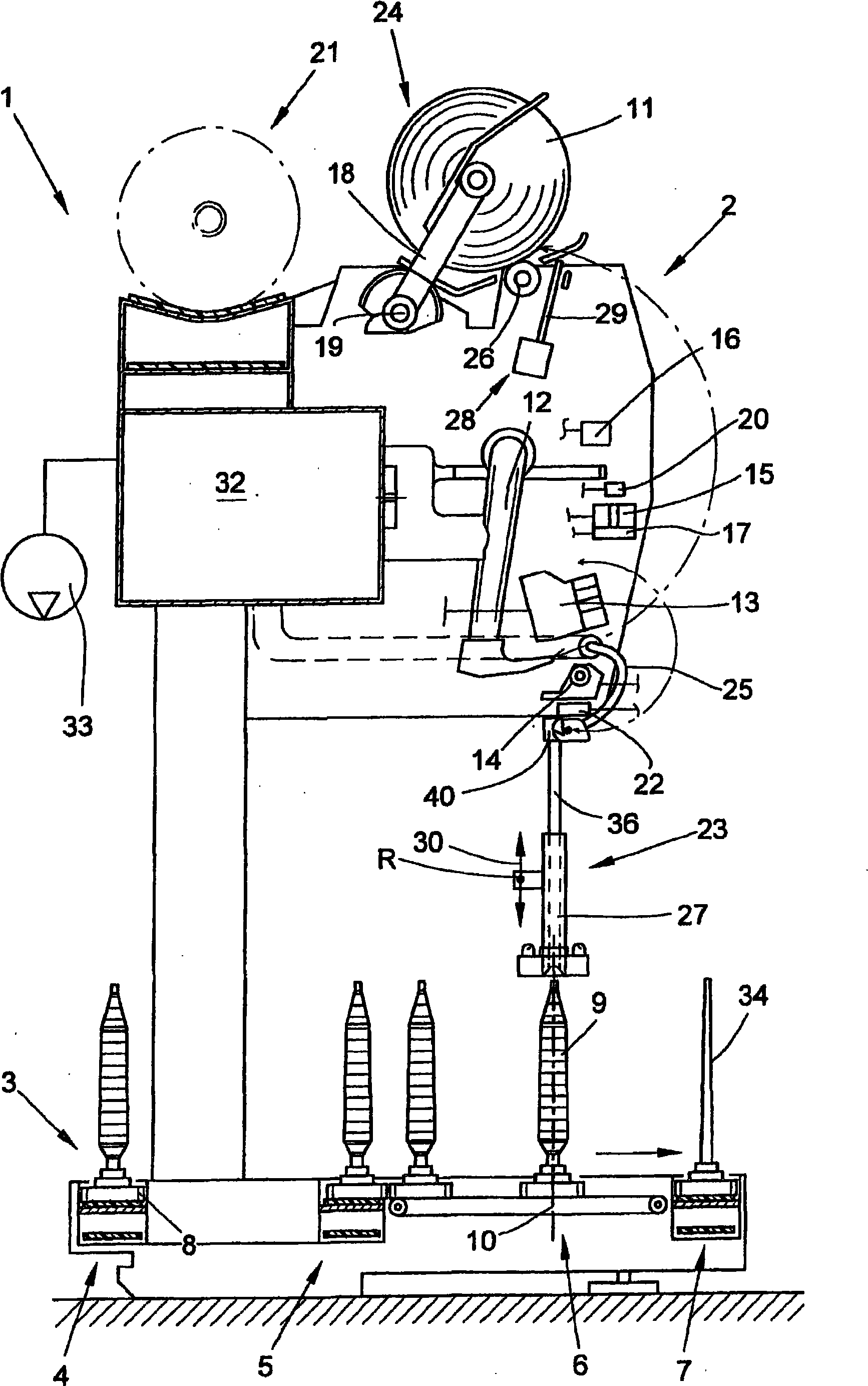
[0033] figure 1 A textile machine for producing cross-wound bobbins, which is referred to as automatic cross-winder 1 in this exemplary embodiment, is shown schematically in side view. This automatic crosswinder 1 has a plurality of stations or winding heads 2 of the same type between its end frames (not shown).

[0034] As known and thus not further described, at the spinning station 2 the spinning bobbin 9 produced on the (not shown) ring spinning machine and having only relatively little yarn material is Rewinding into large-capacity cross-wound bobbins 11, the cross-wound bobbins 11 are then conveyed by means of (not shown) automatically operated service units to a cross-wound bobbin conveying mechanism 21 arranged in the longitudinal direction of the machine and conveyed to A bobbin loading station (likewise not shown) arranged at the end of the machine or the like. In addition, if figure 1As shown, such an automatic cross-winder 1 preferably has a logistics system in ...


PUM


Abstract

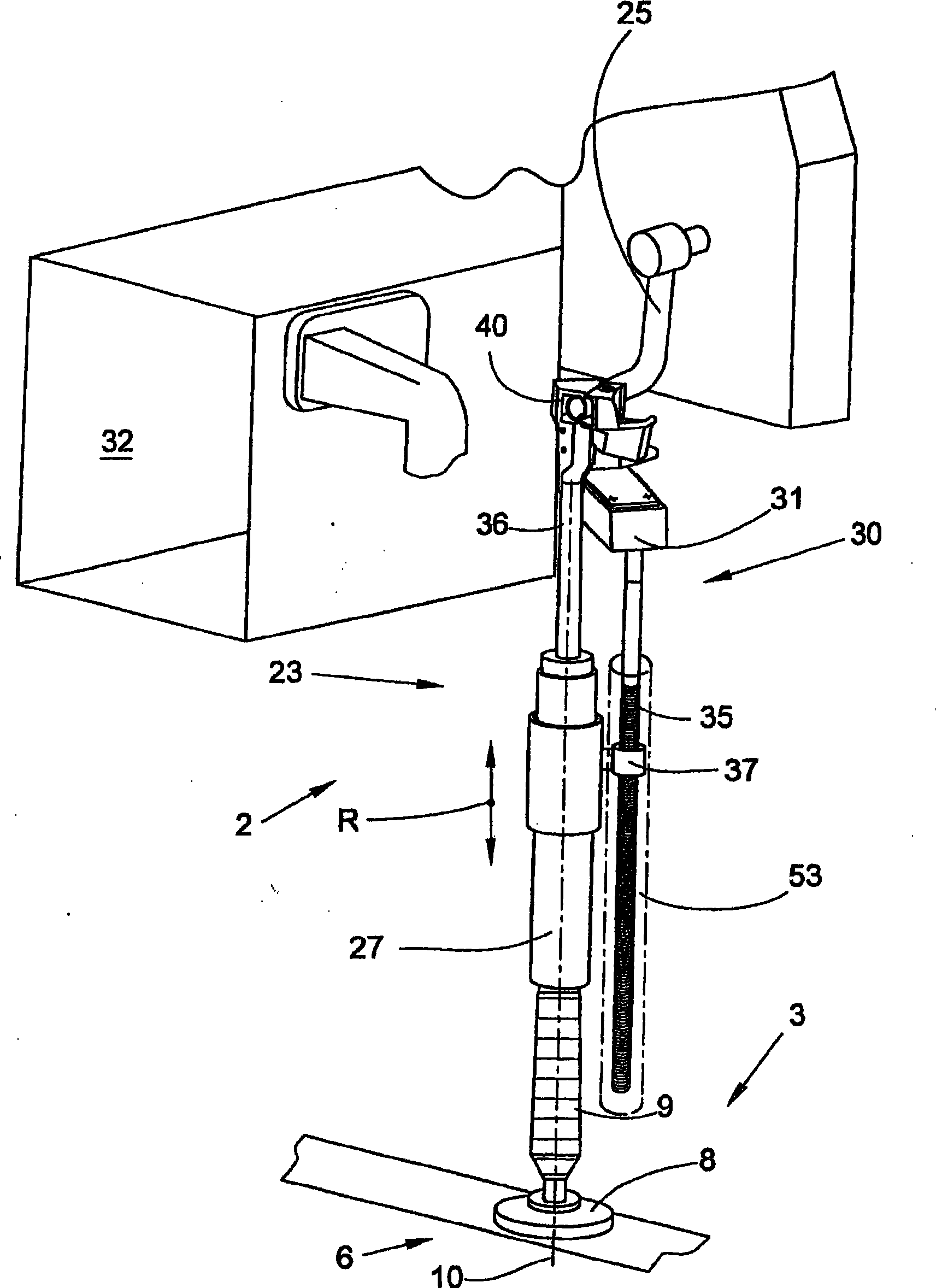
The invention relates to a spindle for a motion gear, in particular, for a wind-off auxiliary device (23) on a winding station (2) of a textile machine (1) producing cross-wound spools. According to the invention, the spindle (35) is a multi-piece component, comprising a long spindle base body (38) and a number of guide segments (39) which may be attached to the spindle base body (38) arranged serially on the spindle base body (38) such as to provide at least one through guide track (47, 48) for a carriage-like motion element (37), provided with guide rollers (51).

Description

technical field [0001] The invention relates to a spindle for a motion transmission according to the preamble of claim 1 . Background technique [0002] In connection with textile machines for producing cross-wound bobbins it has been known for a long time to arrange a device in the region of the winder of these textile machines which improves the withdrawal of the yarn from the spinning bobbin. This arrangement above the spinning bobbin (which is positioned in the spinning position) ensures that the yarn tension is kept at a level that is not harmful to the yarn during rewinding. [0003] Such devices, which are also described as unwinding aids, are described in detail in numerous patent documents, for example in the later published DE 10 2005 018 381 A or DE 4221 559 A1. [0004] The unwinding aid according to DE 10 2005 018 381 A has a vertically displaceable mounted balloon limiter, a tubular yarn guide and an adapter which can be applied during the yarn transport throu...

Claims


Application Information

Patent Timeline
Patent Type & Authority Applications(China)
IPC IPC(8): F16H25/24B65H57/12
CPCB65H57/26F16H25/2261F16H25/24B65H57/12
Inventor 诺伯特·科雷斯
Owner SAURER GERMANY GMBH & CO KG
Why Eureka
Eureka Blog
Learn More