
Down-hole mechanical movable-sieve jig

A moving sieve jig machine and mechanical technology, applied in the direction of solid separation, wet separation, chemical instruments and methods, etc., can solve the problems of large space occupation, easy coal leakage, etc., and achieve reasonable layout, easy installation, and cost reduction Effect

Inactive Publication Date: 2009-07-22
LIAONING TIAN AN TECH CO LTD
View PDF6 Cites 11 Cited by
  • Summary
  • Abstract
  • Description
  • Claims
  • Application Information

AI Technical Summary

Problems solved by technology

[0003] The purpose of the present invention is to provide an improved underground mechanical moving screen jig, which solves the defects of the prior art, such as large space occupation and easy coal leakage, and retains its safety and reliability for underground operations and reduces costs. In addition to the advantages of reducing environmental pollution, its compact structure design, easy installation, and reasonable layout ensure that the moving screen body does not interfere with the operation, the adjustment of coal passing capacity and gangue passing capacity is flexible and reliable, and the separation of lump coal and gangue is accurate. The adaptability matched with the main underground transportation system can significantly improve the discharge quality and sorting efficiency

Method used


Image

  • Down-hole mechanical movable-sieve jig
  • Down-hole mechanical movable-sieve jig
  • Down-hole mechanical movable-sieve jig

Examples


Embodiment Construction

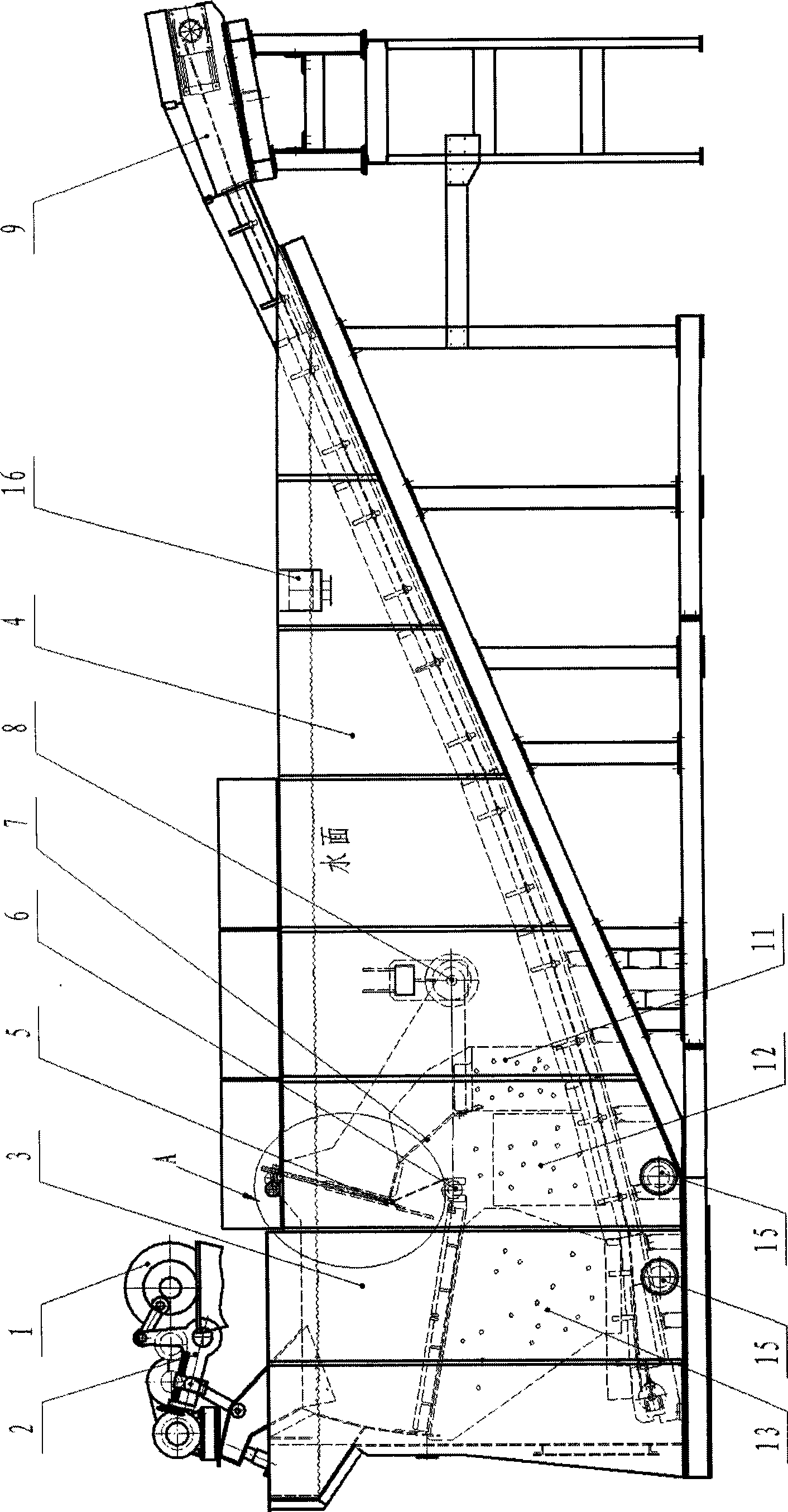
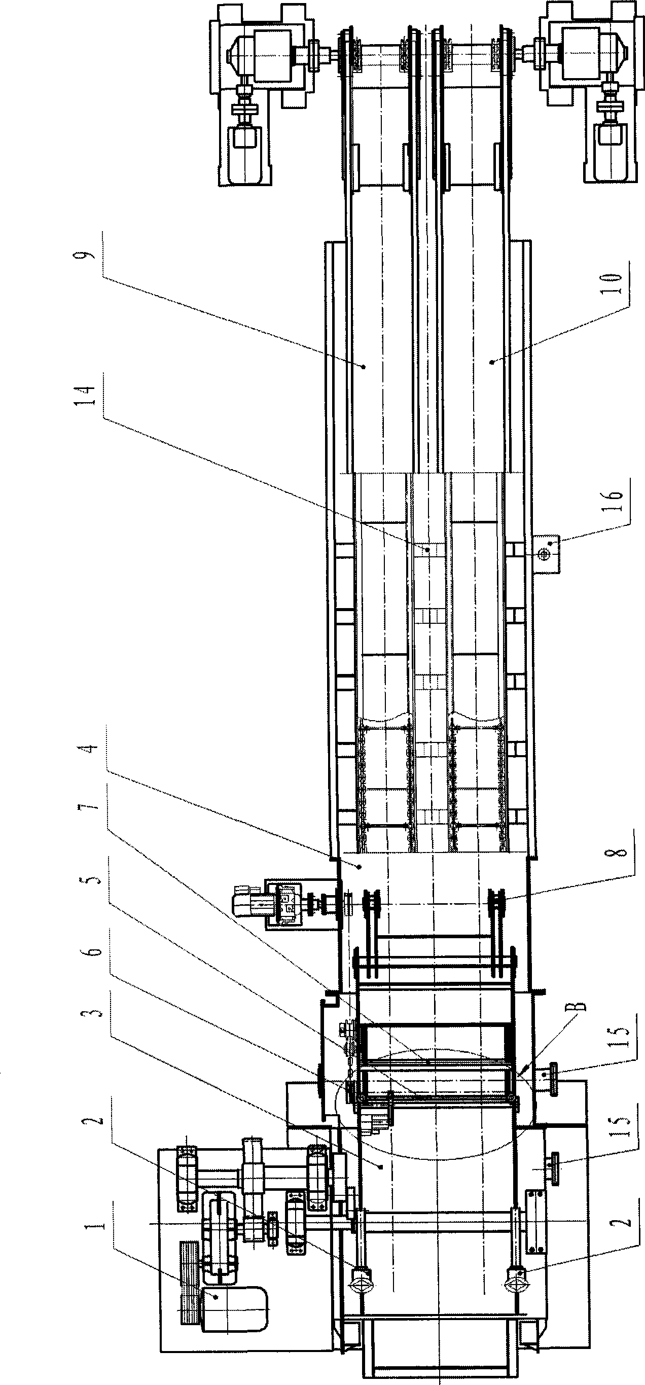
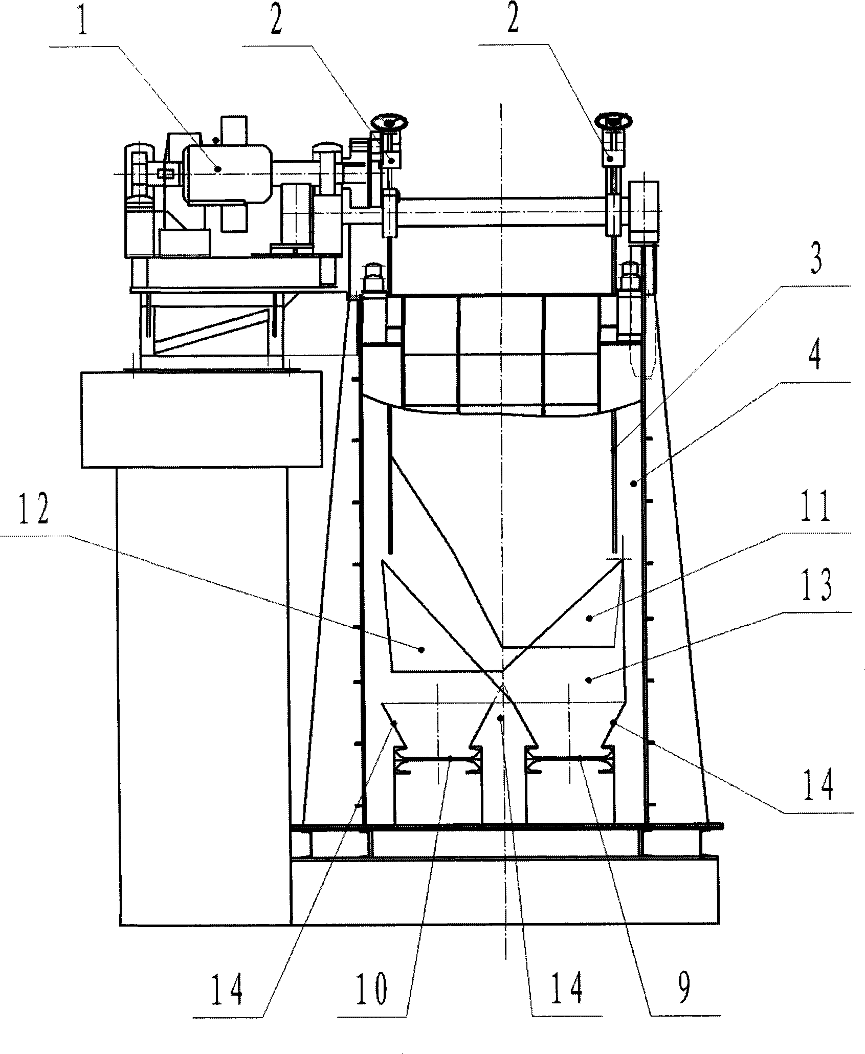
[0016] according to Figure 1-5 The specific structure of the present invention will be described in detail. The downhole mechanical dynamic screen jig includes a box body 4, a moving screen body 3 assembled on the box body 4 and driven by the main drive mechanism 1 and the crank linkage mechanism 2 and installed in the box body 4 through a fixed fulcrum 8, the installation Partition plate 7 and row gangue wheel 6 and material lifting mechanism in moving screen body 3. Wherein the structure of the main drive mechanism 1, the crank linkage mechanism 2 and the movable screen body 3 adopts the structure of the "downhole mechanical movable screen jig" designed by the inventor, and its specification and shape can be determined according to actual use requirements. The bottom of the box body 4 is provided with a flange mouth 15 that can be used for regular water change and desilting of the box body 4, and an overflow port 16 is provided on the upper part, and water is added to the ...


PUM


Abstract

The invention relates to an underground mechanical movable sieve jig, which overcomes the defects of easy coal leakage, and the like in the prior art, and has the advantages of adapting to underground work, having safety and reliability, reducing environmental pollution, and the like. The movable sieve jig comprises a box body, a movable sieve body and a material lifting mechanism. The technical key points comprise: the movable sieve body can be provided with a height-adjustable overflow weir; the material lifting mechanism adopts a block coal scraper conveyer and a recrement scraper conveyer which are arranged in parallel, the after-body of the lifting mechanism is positioned on the bottom end of the box body, and the main body thereof is arranged slantways until the headpiece is above the surface of water; two sides of each scraper conveyer are provided with a material-blocking apron plate; the movable sieve is in transitional connection with the two scraper conveyers through a recrement chute, a block coal chute and a sieved-object chute respectively; and a lower outlet of each chute is aligned in the material-blocking apron plates on two sides of the corresponding conveyer respectively. The movable sieve jig has the advantages of compact structural design, reasonable arrangement, ensured noninterference of the running of the movable sieve, flexible adjustment and reliable running, improves the adaptability to matching with a main underground conveying system, and remarkably improves the quality of the discharged materials and the sorting efficiency.

Description

technical field [0001] The invention relates to a sorting equipment used in underground coal mines, in particular to an underground mechanical dynamic sieve jig suitable for sorting 25-350mm grain size coal. Background technique [0002] Existing moving screen jig mainly has three kinds of structures: one is a hydraulic (electromechanical-hydraulic integration) type moving screen jig, such as the "hydraulic moving screen jig" whose patent announcement number is CN2524865Y, which discloses A hydraulic dynamic screen jigging machine composed of hoist, hydraulic control device, electrical control device, etc. The high frequency of the jigging machine brings insurmountable difficulties to the hydraulic system, frequent failures, difficult operation and maintenance, and operation high cost. The second is a mechanical dynamic sieve jig, such as the "stop-stop reciprocating mechanical dynamic sieve jig" of CN2451234Y, which discloses an intermittent dynamic sieve jig suitable for ...

Claims


Application Information

Patent Timeline
Patent Type & Authority Applications(China)
IPC IPC(8): B03B5/18B03B5/24B03B11/00
CPCB03B2011/006B03B5/18B03B5/24B03B11/00
Inventor 曹树祥曹伟邢成国赵振英
Owner LIAONING TIAN AN TECH CO LTD
Learn More