Technology for manufacturing lock ring for wheeled engineering machinery wheel and shaping mold thereof

A technology for construction machinery and forming dies, applied in the direction of manufacturing tools, forging/pressing/hammering machinery, metal processing equipment, etc., can solve the problem that the shape and size of the workpiece cannot meet the requirements of the drawing design, the elasticity of the workpiece cannot meet the requirements of international standards, Product quality cannot be guaranteed and other problems, to achieve the effect of improving the elasticity of the lock ring, reducing the deformation resistance, and improving production efficiency

Inactive Publication Date: 2009-07-22
HONGYUAN JINGGONG WHEEL CO LTD
View PDF0 Cites 7 Cited by
  • Summary
  • Abstract
  • Description
  • Claims
  • Application Information

AI Technical Summary

Problems solved by technology

[0003] This manufacturing process has serious deficiencies in actual production, which are mainly reflected in the following aspects: First, because the tensile strength of No. 50 steel at room temperature is 630Mpa, and the elastic limit is relatively high, it is difficult to produce plasticity during cold pressing Therefore, the shape and size of the workpiece after shaping cannot meet the drawing design requirements, and the product quality cannot be guaranteed; second, because the finishing process is manual, the workpiece accuracy is poor, and the production efficiency is low; Two heat treatments, complex production process, high manufacturing cost, and in the process of normalizing, due to the slow cooling rate, the elasticity of the workpiece after normalizing cannot meet the requirements of international standards

Method used


Image

  • Technology for manufacturing lock ring for wheeled engineering machinery wheel and shaping mold thereof
  • Technology for manufacturing lock ring for wheeled engineering machinery wheel and shaping mold thereof

Examples


Embodiment Construction

[0030] In order to enable those skilled in the art to better understand the solution of the present invention, and to make the above-mentioned purpose, features and advantages of the present invention more obvious and comprehensible, the present invention will be further described in detail below in conjunction with the accompanying drawings and embodiments.

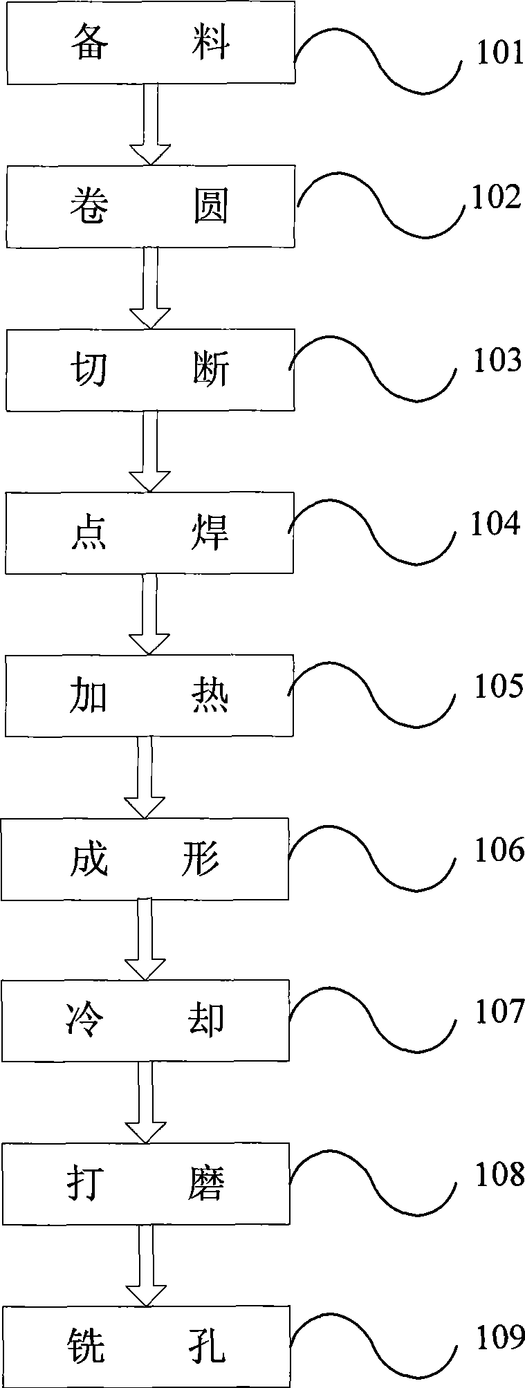
[0031] Such as figure 1 As shown, the embodiment of the wheel lock ring manufacturing process provided by the invention includes the following steps:

[0032] S101 Material preparation Rolling the steel billet into a long material with a prefabricated lock ring section structure shape;

[0033] S102 roll round Make the long material roll into a spiral coil material;

[0034] Utilize the existing coiling machine to make the long material roll into a helical coil material, the helical diameter of the helical coil material is substantially the same as that of the prefabricated lock ring.

[0035] S103 Cutting: Cut the spi...


PUM

PropertyMeasurementUnit
tensile strengthaaaaaaaaaa

Abstract

The invention discloses a process and a forming die for manufacturing a lock ring for wheels of a wheel type construction machinery vehicle, and belongs to the technical field of construction machinery. The process comprises the following working procedures: winding into a circle, wherein long materials are wound into spiral ring materials; cutting, wherein the spiral ring materials are cut into single multiple length ring materials according to the specification of a prefabricated lock ring; performing spot welding, wherein spot welding is performed on cuts of the single multiple length ring materials to form an enclosed ring blank; heating, wherein the ring blank is heated to be between 680 and 720 DEG C to form a heating workpiece; forming, wherein dimensions and size of the heating workpiece are finished by the forming die to form the workpiece; cooling, wherein the formed workpiece is cooled directly in air; polishing, wherein welding spots of the cooled workpiece are polished to be neat, bright and clean; and milling a hole, wherein the hole on the polished workpiece is milled by a miller to manufacture a finished product lock ring. The invention is suitable for manufacturing the lock ring for the wheels of the wheel type construction machinery vehicle.

Description

technical field [0001] The invention relates to a lock ring manufacturing process and a forming die thereof, in particular to a lock ring manufacturing process for wheel engineering machinery wheels and a forming die thereof, belonging to the technical field of engineering machinery. Background technique [0002] The existing locking rings for wheel construction machinery wheels are generally made of No. 50 carbon structural steel through a secondary heat treatment process. The process flow is: scribing→rolling→annealing→cutting→cold shaping→artificial finishing →Milling →Normalizing. [0003] This manufacturing process has serious deficiencies in actual production, which are mainly reflected in the following aspects: First, because the tensile strength of No. 50 steel at room temperature is 630Mpa, and the elastic limit is relatively high, it is difficult to produce plasticity during cold pressing Therefore, the shape and size of the workpiece after shaping cannot meet the...

Claims


Application Information

Patent Timeline
Patent Type & Authority Applications(China)
IPC IPC(8): B23P15/00B21J13/02
Inventor 陈汉杰马会民孙爱军黄洪亮袁优良唐华祥
Owner HONGYUAN JINGGONG WHEEL CO LTD
Why Eureka
Try Eureka