High-frequency coil structure capable of producing six silicon cores and other crystal material at the same time

A high-frequency coil and crystal material technology, applied in the direction of coil device, crystal growth, single crystal growth, etc., can solve the problems of unpredictable current operation, increase in the number of defective products, large disparity in seed crystal diameter, etc. The effect of defective rate, reduction of production cost and improvement of energy utilization

Active Publication Date: 2009-07-22
LUOYANG JINNUO MECHANICAL ENG
View PDF2 Cites 58 Cited by
  • Summary
  • Abstract
  • Description
  • Claims
  • Application Information

AI Technical Summary

Problems solved by technology

[0006] Through the use of the above-mentioned patents for the past two years, the current running around the inner hole can not achieve the expected purpose. As the structure described in the above two patent application documents, the inner holes are arranged in a radial shape, and there is a problem of connecting oblique openings except for the middle part. There are more currents in the inner holes, and the surrounding currents of the other five inner holes are affected by the principle of high-frequency current operation, so that the temperature of most inner holes is much lower than the temperature of the inner holes near or connected to the oblique opening (that is, the current takes a shortcut ), due to the short-cut phenomenon of the current, the result is that the diameter of the lifted crystals is very large, resulting in an increase in the number of defective products

Method used


Image

  • High-frequency coil structure capable of producing six silicon cores and other crystal material at the same time
  • High-frequency coil structure capable of producing six silicon cores and other crystal material at the same time
  • High-frequency coil structure capable of producing six silicon cores and other crystal material at the same time

Examples


Embodiment Construction

[0018] The present invention can be explained in more detail with reference to the following examples; however, the present invention is not limited to these examples.

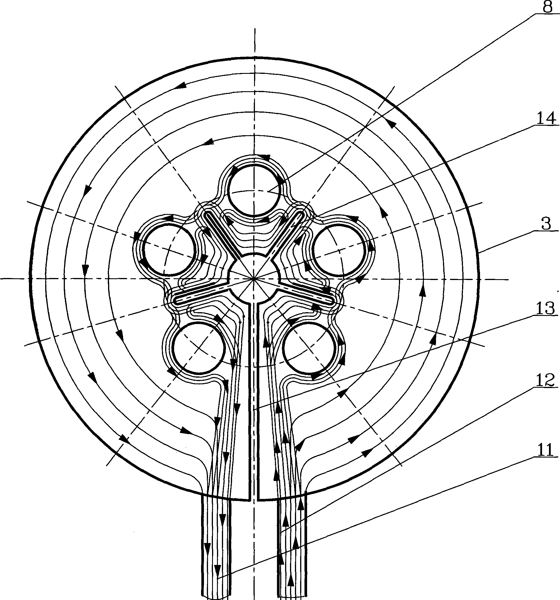
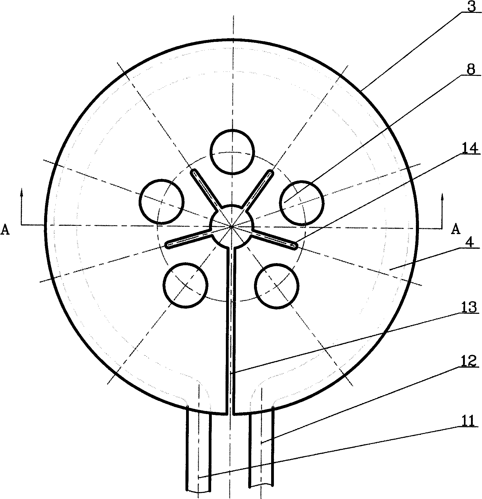
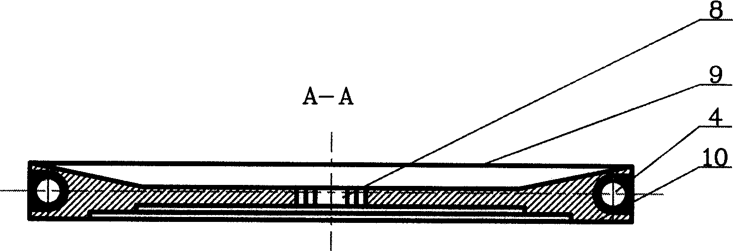
[0019] exist figure 1 , 2 , 3, and 4; a high-frequency coil structure that can simultaneously produce six silicon cores and other crystal materials, the high-frequency coil structure is provided with current delivery and cooling water delivery copper pipe A11 and current Conveying and cooling water conveying copper pipe B12, the upper part of the high-frequency coil of the high-frequency coil 9 is a slope that sinks inward toward the center, the lower part of the high-frequency coil of the high-frequency coil is provided with a trapezoid that sinks inward toward the center, and the cooling water channel 4 rings are buried Outside the high-frequency coil 3; the high-frequency coil structure includes radial shunt grooves 14 for current 15 conduction, six inner holes 8 are provided with an inner hole 8 in the mi...


PUM


Abstract

The invention provides a high-frequency coil structure which can produce six silica cores and other crystal materials simultaneously, relating to the technical field of high-frequency coils. The high-frequency coil structure comprises a radial shunt trough (14) which is used for diversion of current (15), and six internal holes (8), wherein, one internal hole is arranged at the middle part and other five internal holes are uniformly distributed around the middle internal hole in a petal-shape; an inclined opening (13) at one side of a copper pipe A(11) for conveying current and cooled water and a copper pipe B(12) for conveying current and cooled water is connected and communicated with the middle internal hole; the radial shunt trough extends out from the middle internal hole to a position between every two internal holes except the inclined opening; the inclined opening is connected with the middle internal hole; and the radial shunt trough is radially distributed between every two peripheral internal holes by the middle internal hole, thus leading the current to uniformly run by surrounding the six internal holes under the shunt effect of the shunt trough during the running process and achieving the objects that the current is uniformly distributed around the six internal holes.

Description

Technical field: [0001] The invention relates to the technical field of high-frequency coils, in particular to a new type of high-speed coil that can distribute current evenly around the inner hole, heat silicon cores or other crystal materials evenly through the current, and simultaneously produce six silicon cores and other crystal materials. Frequency coil structure. Background technique: [0002] At present, silicon cores are used in a huge amount in China; in the existing process of producing silicon cores, monocrystalline silicon and other material crystal zone melting methods, most of them use a monocular high-frequency coil, and its working principle is as follows: When working, pass high-frequency current to the high-frequency coil, so that the high-frequency coil generates current to inductively heat the raw material rod, and the upper end of the heated raw material rod forms a melting zone, and then inserts the crystal into the melting zone, and slowly lifts the c...

Claims


Application Information

Patent Timeline
Patent Type & Authority Applications(China)
IPC IPC(8): C30B13/20C30B15/14H05B6/42
Inventor 刘朝轩
Owner LUOYANG JINNUO MECHANICAL ENG
Why Eureka
Try Eureka