Pile forming apparatus and method for mud-jacking inner-ramming pedestal pile

A bottom-expanding pile and pile-forming technology, which is applied to sheet pile walls, buildings, and foundation structure engineering, can solve problems such as failure to pull out the outer pipe, broken piles, side friction and poor pull-out resistance

Inactive Publication Date: 2009-07-22
李永刚
View PDF7 Cites 8 Cited by
  • Summary
  • Abstract
  • Description
  • Claims
  • Application Information

AI Technical Summary

Problems solved by technology

[0004] The purpose of the present invention is to solve the problem that the side friction and pull-out resistance of the existing internal tamping piles are still relatively poor, and the concrete of the pile body is poured underground, which is easy to cause necking and broken piles, low construction efficienc

Method used


Image

  • Pile forming apparatus and method for mud-jacking inner-ramming pedestal pile
  • Pile forming apparatus and method for mud-jacking inner-ramming pedestal pile
  • Pile forming apparatus and method for mud-jacking inner-ramming pedestal pile

Examples


specific Embodiment approach 1

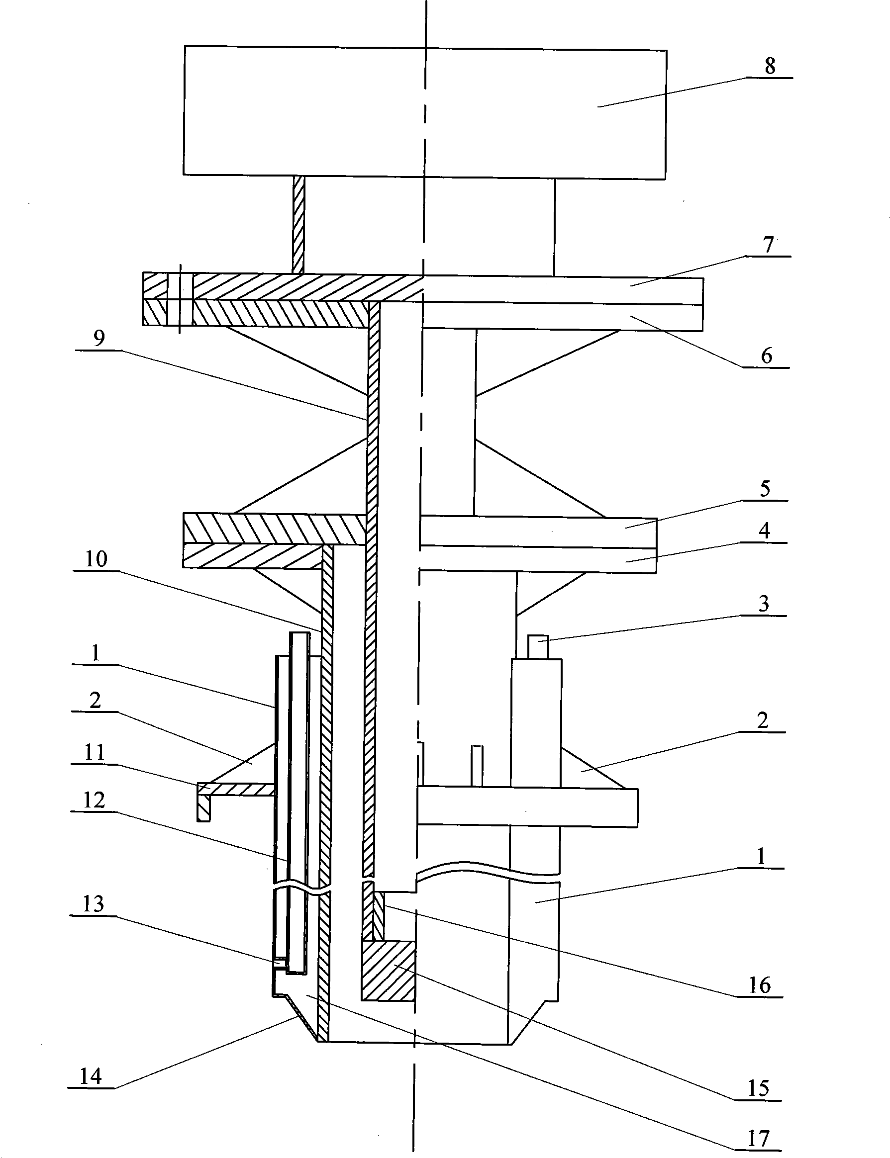
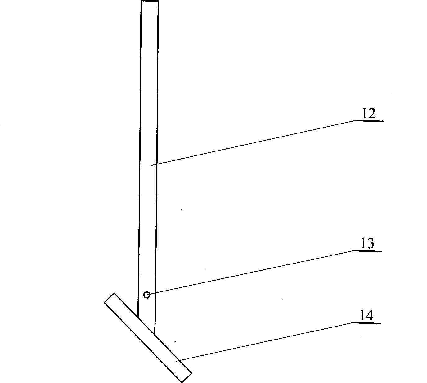
[0006] Specific implementation one: (see Figure 1 to Figure 3 ) This embodiment includes a closed cavity outer steel plate 1, a grouting port 3, an outer tube flange 4, an inner tube lower flange 5, an inner tube upper flange 6, a hammer body flange 7, a hammer 8, an inner tube flange Tube 9, outer tube 10, sealing disc 11, grouting tube 12, slurry outlet 13, lower sealing plate 14 of the sealing cavity, cylindrical body 15 and outer tube sealing cavity 17, the lower end of hammer 8 is fixedly connected with a hammer body flange Disc 7, the upper end of the inner tube 9 is fixedly connected with the inner tube upper flange 6, the inner tube upper flange 6 is connected with the hammer body flange 7, and the middle and upper part of the inner tube 9 is fixedly connected with the inner tube lower flange Plate 5, the upper end of the outer tube 10 is fixedly connected with the outer tube flange 4, the outer tube flange 4 is in contact with the lower flange 5 of the inner tube, an...

specific Embodiment approach 2

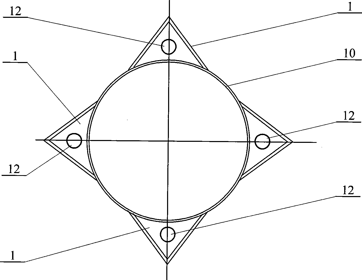
[0007] Specific implementation two: (see figure 1 ) The closed cavity outer steel plate 1 in this embodiment is composed of two to four outer closed cavity steel plates 1. Two to four closed cavity outer steel plates 1 are arranged on the outer wall of the outer tube 10, and each closed cavity outer steel plate 1 is provided with one to two grouting pipes. 12. Others are the same as the first embodiment.

specific Embodiment approach 3

[0008] Specific implementation three: (see figure 1 ) The closed cavity outer steel plate 1 in this embodiment consists of two closed cavity outer steel plates 1 symmetrically arranged on the outer wall of the outer tube 10 . Others are the same as the first embodiment.


PUM


Abstract

The invention provides a pile-forming device for a grouting internal-ramming pedestal pile and a pile-forming method thereof, relating to a pile-forming device and a method. The device and the method aim at solving the problems that the existing internal-ramming pile has bad side friction and anti-pulling capability, is easy to generate the necking and breaking problem and has low construction efficiency. The injection pipe of the device is fixed in an external steel plate with a sealed cavity; the bottom end of the external steel plate with the sealed cavity is fixedly provided with a lower sealing plate with a sealed cavity; the invention is provided with four methods as follows: method one: an external pipe is impacted by a hammer, meanwhile, the grout is injected into the injection pipe by a pump, with the injection pressure of 0.3-10MPa; method two: an internal pipe is impacted by a diesel hammer, a hydraulic hammer or a vibration hammer and the filling material is impacted; method three: the external pipe and a pre-fabricated pile are impacted to a design depth by the diesel hammer, the hydraulic hammer or the vibration hammer; method four: the pre-fabricated pile is impacted into the pile hole, wherein, the diameter of the external pipe is less than or equal to the maximum internal tangent round of the pre-fabricating pile. The device has high construction efficiency and is suitable for various soil qualities. The method reduces the generation of necking and breaking, and improves the bearing capability by more than 30%.

Description

technical field [0001] The invention relates to a pile forming device and a pile forming method. Background technique [0002] At present, the widely used rammed and expanded pile can make full use of the bearing layer at the end of the pile to increase the bearing capacity, thereby reducing the length of the pile and reducing the cost. However, with the gradual passage of application time, some deficiencies of rammed piles have gradually emerged: 1. Because the length of the pile is too short, generally not more than 10 meters, the soil qsik (standard value of ultimate lateral resistance) between the piles in this interval ) is generally small, and although the soil between the piles is also squeezed, the lateral friction and pull-out resistance are still poor. 2. Because the concrete of the pile body is poured underground, it is easy to produce necking and broken piles. 3. Generally, the tamping and expanding machine uses a hoisting and hanging rammer to ram and expand b...

Claims


Application Information

Patent Timeline
IPC IPC(8): E02D5/44
Inventor 李永刚王锐张序明
Owner 李永刚
Why Eureka
Try Eureka