Multi operation-channel celioscope system with sheath tube

A technique for operating channels and laparoscopy, which is applied in the field of multi-operating channel laparoscopic systems, can solve problems such as no clinical use, and achieve the effect of reducing surgical incisions and simple operation.

Active Publication Date: 2009-07-29
GUANGZHOU BAODAN MEDICAL INSTR TECH
View PDF0 Cites 8 Cited by
  • Summary
  • Abstract
  • Description
  • Claims
  • Application Information

AI Technical Summary

Problems solved by technology

Due to the external conflict and mutual interference between the surrounding instruments and the puncture cannula, the current

Method used


Image

  • Multi operation-channel celioscope system with sheath tube
  • Multi operation-channel celioscope system with sheath tube
  • Multi operation-channel celioscope system with sheath tube

Examples


Embodiment 1

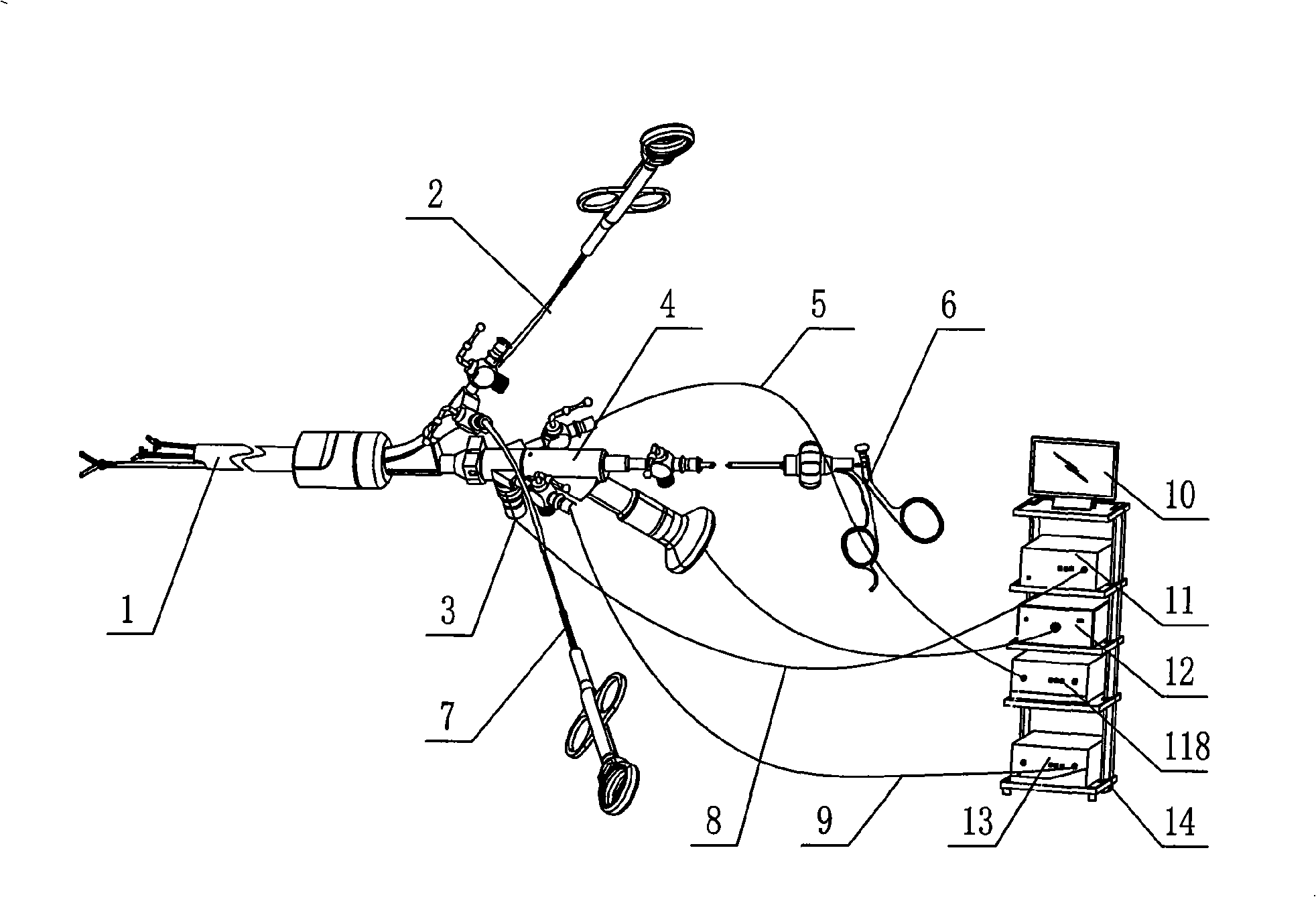
[0025] Such as figure 1 As shown, the multi-operation channel laparoscope system with a sheath according to the present invention includes a laparoscope sheath 1 with two operation channels, a laparoscope 4, and a cold light source interface 44 connected to the laparoscope 4 using an optical fiber line 3 And cold light source host 11, use data line 8 to connect the eyepiece input end 48 of laparoscope 4 and image processing center 12, the independent water inlet channel 45 of laparoscope (or gas-peritoneum machine interface) through connecting pipe 5 and gas-peritoneum machine 118 phases Connection, water outlet channel 46 (or insufflation machine interface) is connected to flushing suction device 13, image processing center 12 rear panel to connect monitor 10 through connecting pipe 9, monitor 10, cold light source host 11, image processing center 12 and flushing suction Devices 13 are placed in special trolleys 14 respectively.

[0026] Depend on figure 1 It can be seen th...

Embodiment 2

[0034] This embodiment is basically the same as Embodiment 1, the difference is: as Figure 8 , Figure 9 As shown, the laparoscopic sheath main body 17 is also provided with an insufflation machine interface 171 for connecting with the insufflation machine 118, and the insufflation machine interface 171 is connected with the insufflation machine 118 through a connecting tube 119, and the abdominal cavity The independent water inlet channel 45 and the water outlet channel 46 of the mirror 4 are connected to the flushing suction device 13 through the connecting pipes 5 and 8, and the main difference from the first embodiment is that the insufflation machine 118 is directly connected with the laparoscopic sheath tube main body 1 . Such as Figure 10 As shown, the outlet of the sheath tube end of the insufflation machine interface 171 is 1711 , and the gas entering the sheath tube of the insufflation machine 118 through the connecting tube 119 and the insufflation machine inter...


PUM

PropertyMeasurementUnit
Diameteraaaaaaaaaa

Abstract

The invention belongs to the field of medical apparatuses, and in particular discloses a multi-operation channel laparoscope system with a sheathing canal, which comprises a laparoscope with an operation channel, a laparoscope sheathing canal with more than two operation channels and a multi-operation channel laparoscope image system, wherein the laparoscope comprises an endoscope main body, an operation channel communicated with the endoscope main body, a water inlet channel, a water outlet channel, an ocular input end, a cold light source input end, an endoscope end part and a hard endoscope front end part. The multi-operation channel laparoscope system enters an abdominal cavity from a natural orifice (the umbilical region), under the monitoring of a laparoscope image pickup system, various laparoscope surgery apparatuses with different shapes and different performances are inserted through the multi-channel laparoscope sheathing canal and a plurality of the operation channels of the laparoscope to carry out various minimally invasive surgeries, and an umbilical region cut is stitched after the surgeries. The multi-operation channel laparoscope system has the advantages of surgery cut reduction and simple and safe operation, and avoids the external conflicts between the laparoscope apparatus and the sheathing canal and the laparoscope. The multi-operation channel laparoscope system can truly achieve scarless surgeries, and reduce the surgery wounds and pain of patients to the minimum.

Description

technical field [0001] The invention belongs to the field of medical instruments, and is a core medical tool for modern medicine to carry out endoscopic surgery through natural cavity and abdominal wall scarless surgery, in particular a multi-operation channel laparoscope system with a sheath. Background technique [0002] Laparoscope is a widely used medical device for examination, diagnosis and treatment of abdominal and pelvic lesions. Compared with open surgery, it has many advantages such as less trauma, less pain, faster recovery, fewer complications, beauty, and safety. [0003] However, the current laparoscopic surgery mostly uses 2 to 4 holes in the abdominal wall. The advantage is that it can avoid leaving long strips of scars on the patient's abdomen, but there are still 2 to 4 scars with a length of 1 to 2 cm in the abdomen. The linear scars on the skin affect the cosmetic effect to a certain extent and increase the trauma to the abdominal wall. With the contin...

Claims


Application Information

Patent Timeline
IPC IPC(8): A61B1/313A61B17/94
Inventor 乔铁
Owner GUANGZHOU BAODAN MEDICAL INSTR TECH
Why Eureka
Try Eureka