Two-stage type blowing breeze method and apparatus for blast furnace

An injection device, two-stage technology, used in blast furnaces, combustion methods, blast furnace details, etc.

Inactive Publication Date: 2009-07-29
NORTHEASTERN UNIV
View PDF1 Cites 19 Cited by
  • Summary
  • Abstract
  • Description
  • Claims
  • Application Information

AI Technical Summary

Problems solved by technology

[0009] 1. The special equipment or devices set up for the second stage of pulv...

Method used


Image

  • Two-stage type blowing breeze method and apparatus for blast furnace

Examples


Embodiment Construction

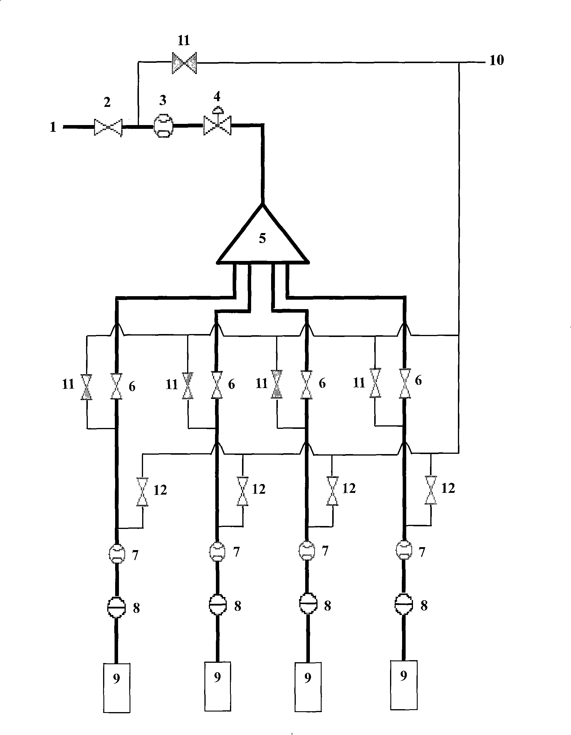
[0030] The volume of a blast furnace in a steel plant is 1800m 3 , In the early stage of implementing the two-stage injection, due to the unreasonable injection equipment and improper control of related parameters, gun blocking accidents occurred frequently (sometimes up to 8 times / day), and the desired effect was not received. Adopt the technology of this invention, its blowing equipment and attached figure 1 The device shown is the same, and there are four spray guns, which are symmetrically distributed on the same circle along the section of the furnace body at the lower part of the blast furnace shaft and above the reflow zone. And properly controlled the operating parameters of the second injection system, among which:

[0031] 1. The injection volume of a single gun is 350-650kg / h, with an average of 402kg / h;

[0032] 2. Control the solid-gas ratio to ≤20kg / kg through secondary air supply;

[0033] 3. Control the injection pressure P 风 +50kPa~P 风 +150kPa, the averag...


PUM


Abstract

The invention relates to a method for two-stage coal injection in blast furnace ironmaking and a device thereof. The invention is characterized in that the inventive two-stage coal injection device provided with a special distributor, an inert gas special pipeline, a plurality of control valves, a flowmeter and a control meter is utilized, fixed operational programs are executed and partial technological parameters are controlled, thus realizing the two-stage coal injection of the blast furnace; through practical production verification for 40 days, by adopting the device and method, blockage of injection guns is effectively avoided; the average coal ratio of the blast furnace is increased by 11.35kg/tHM; and the coke ratio is reduced by 9.87kg/tHM.

Description

Technical field: [0001] A method and device for two-stage pulverized coal injection in blast furnace ironmaking. technical background [0002] Blast furnace ironmaking is and will always be the main process of producing molten iron in iron and steel smelting now and in the future, with incomparable production advantages. And the process of using blast furnace tuyeres as injection ports to inject pulverized coal into the blast furnace has been implemented for many years, and pulverized coal has replaced part of the coke and achieved positive smelting effects. [0003] In 2003, a patented technology (patent number: ZL00123294.0) of "two-stage pulverized coal injection process for blast furnace ironmaking" appeared, which can inject pulverized coal to the upper part of the blast furnace remelting zone, the furnace waist or the lower part of the furnace shaft , so as to reduce the local excessive powder accumulation in front of the tuyere and in the drip zone, reduce the total ...

Claims


Application Information

Patent Timeline
IPC IPC(8): C21B5/00C21B3/02C21B7/16F23K3/02
Inventor 沈峰满杨文光姜鑫张正好丁智敏刘代德
Owner NORTHEASTERN UNIV
Why Eureka
Try Eureka