

Humidification system
A humidification system and object technology, applied in air humidification systems, air conditioning systems, natural cooling systems, etc., can solve the problems of increasing the diffusion range of humidified air, unable to give misty water to objects, etc., so as to improve the atomization ability and The effect of charging ability and power consumption restraint
- Summary
- Abstract
- Description
- Claims
- Application Information
AI Technical Summary
Problems solved by technology
Method used
Image

Examples
Embodiment approach 1
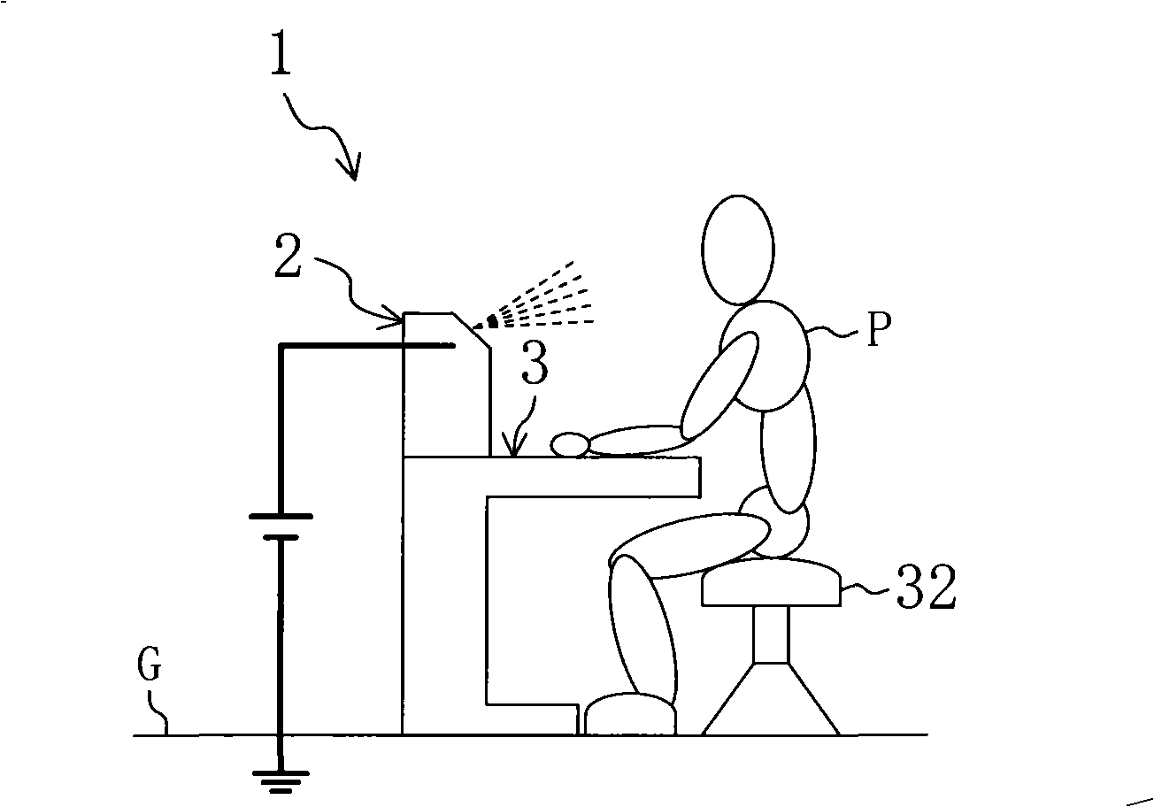
[0073] figure 1 The humidification system 1 according to Embodiment 1 of the present invention is shown. The humidification system 1 includes an electrostatic spray device 2 that releases a charged mist of water.
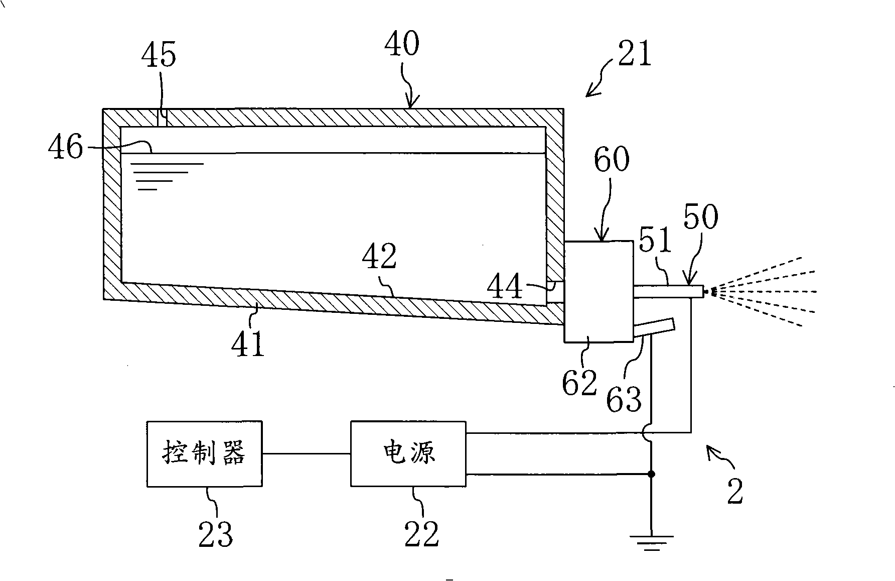
[0074] The above-mentioned electrostatic spraying device 2, such as figure 2 As shown, it includes a spray tube head 21 (tube head=cartridge), a power supply 22 and a controller 23 . This electrostatic spray device 2 is installed on the desktop 3 and supplies mist water to the user P who uses the desktop 3 . This electrostatic spray device 2 constitutes a charged atomizer.
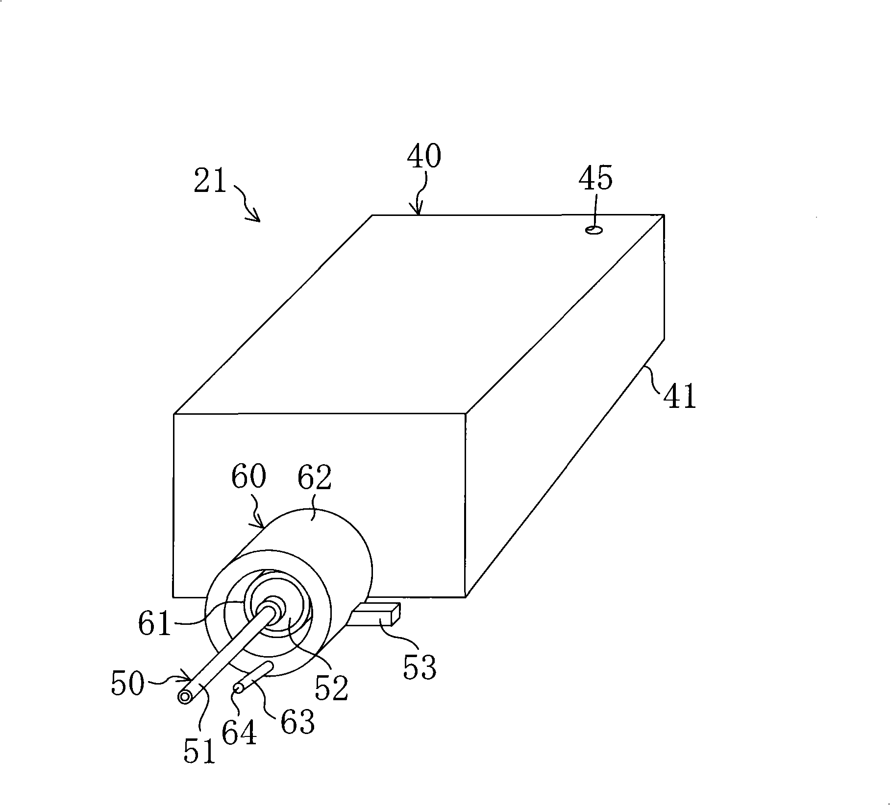
[0075] Such as image 3 , Figure 4 As shown, the spray nozzle head 21 includes a solution tank 40 , a nozzle unit 50 , an electrode holder 60 , and a rod electrode 63 .
[0076] The solution tank 40 described above includes a tank body 41 . The tank body 41 is formed as a hollow container approximately in the shape of a flat cube. On the top plate of the tank body 41, a vent hole 45 is...
Embodiment approach 2
[0101] Next, humidification system 201 according to Embodiment 2 of the present invention will be described. This humidification system 201 is different from the first embodiment described above in that an object such as a person is grounded. Also, the same configurations as those in Embodiment 1 are denoted by the same reference numerals, and description thereof will be omitted.
[0102] Humidification system 201 according to Embodiment 2 is, for example, Figure 8 As shown, an electrostatic spray device 2 and a conductive table 203 for grounding a person P as an object are included.
[0103] The above-mentioned conductive table 203 has a conductive blanket (not shown) that is grounded to the ground plane G on its top plate. That is, when the user P of the conductive table 203 touches the conductive blanket, the user P is grounded. This conductive table 203 constitutes an object grounder. Yet, Figure 8 , is a diagram omitting the conductive blanket and its terminals, to...
Embodiment approach 3
[0111] Next, humidification system 301 according to Embodiment 3 of the present invention will be described. This humidification system 301 is different from the first embodiment described above in that it charges an object such as a person. Also, the same configurations as those in Embodiment 1 are denoted by the same reference numerals, and description thereof will be omitted.
[0112] The humidification system 301 according to Embodiment 3 is, for example, Figure 10 As shown, an electrostatic spray device 2 and a charging table 303 for charging a person as an object are included.
[0113] The above-mentioned electrostatic spraying device 2 has the same configuration as that of the above-mentioned first embodiment.
[0114] The above-mentioned conductive table 303 has a table body 330 and a power supply 333 . The negative terminal of the power supply 333 is electrically connected to the desk main body 330 and the positive terminal of the power supply 333 is grounded, so ...
PUM
 Abstract
Description
Claims
Application Information